Interface cable, Connecting the interface cable – H3C Technologies H3C MSR 50 User Manual
Page 65
2-45
Figure 2-57 SIC-2BS panel
Figure 2-58 SIC-1BU panel
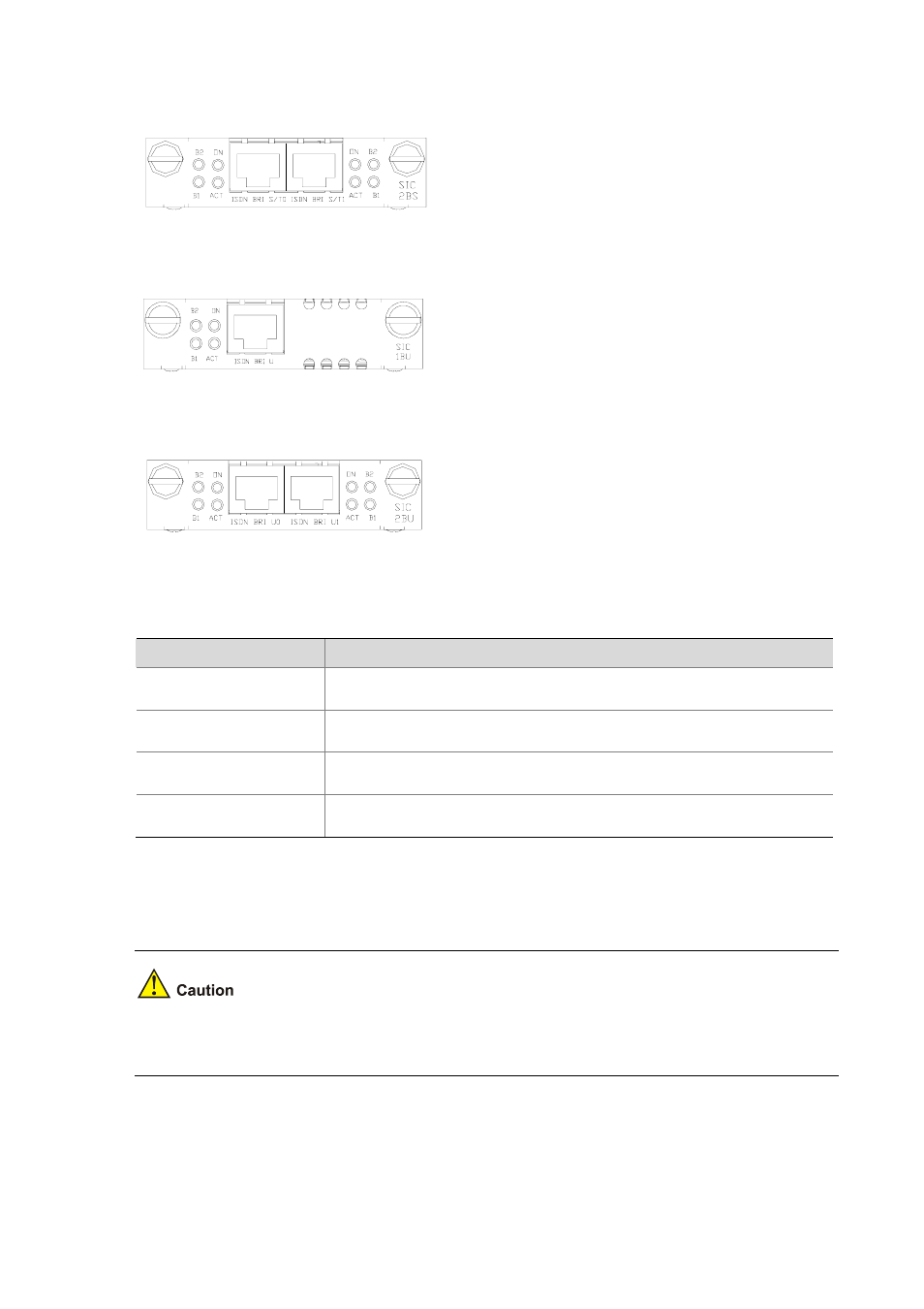
Figure 2-59 SIC-2BU panel
The following table describes the LEDs on SIC-1BS/SIC-2BS and SIC-1BU/SIC-2BU panels.
Table 2-35 LEDs on SIC-1BS/SIC-2BS and SIC-1BU/SIC-2BU panels.
LED
Description
B1
z
OFF indicates the B1 channel is idle.
z
Blinking indicates the B1 channel is being used for data communication.
B2
z
OFF indicates the B2 channel is idle.
z
Blinking indicates the B1 channel is being used for data communication.
ACT
z
OFF indicates the inactive state.
z
Steady ON indicates the active state.
ON
z
OFF indicates the interface module is powered off.
z
ON indicates the interface module is powered on.
Interface cable
Both SIC-1BS/SIC-2BS and SIC-1BU/SIC-2BU use the telephone cable with ferrite core.
The corresponding cables of SIC-1BS/SIC-2BS and SIC-1BU/SIC-2BU are included in their standard
shipment packages.
Connecting the interface cable