Interface leds, Interface cable, Connecting the interface cable – H3C Technologies H3C MSR 50 User Manual
Page 85
2-65
Interface LEDs
The following figure shows the SIC-AUDIO panel.
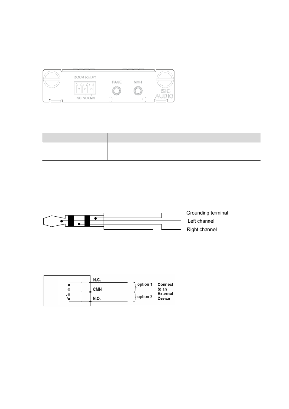
Figure 2-80 SIC-AUDIO panel
The following table describes the LEDs on the SIC-AUDIO panel.
Table 2-50 Description of the LEDs on SIC-AUDIO panel
LED
Description
LINK
z
ON means a standard audio connector has been inserted.
z
OFF means no audio connector has been inserted in the SIC-AUDIO
terminal or a wrong cable is inserted.
Interface cable
1) The MOH and PAGE interfaces of the SIC-AUDIO connect to peer devices through an audio cable
with standard audio connectors. The following figure shows a standard audio connector.
Figure 2-81 Standard audio connector
2) The DOOR RELAY interface of the SIC-AUDIO connects to a peer device through a cable with a
3-pin PHOENIX connector.
Figure 2-82 Output signals of the 3 pin PHOENIX connector
Connecting the interface cable
1) Connect the MOH interface
Plug one end of the standard audio connector into the MOH interface, and connect the other end to the
audio output device. Keep the device outputting music or broadcasting signals. Then, through the MOH
interface, the router obtains the audio signals for call background music, call waiting music, or waiting
music of joining a telephone conference.
2) Connect the PAGE interface