Connecting the interface cable – H3C Technologies H3C MSR 50 User Manual
Page 40
2-20
E1 cable, coaxial connector, network interface connector and 75ohm-to-120ohm adapter are optional.
Order them together with SIC-EPRI. By default, they are not supplied.
Connecting the interface cable
When using E1 cable outdoors, you are recommended to install a special lightning arrester on the input
end of the cable in order to avoid lightning more effectively.
If the SIC has been properly installed, follow these steps to connect the cable:
Step1 Check the type of E1 cable and correctly set the DIP switch (the ex-factory setting of E1/CE1/PRI
interface impedance is 75-ohm);
Step2 Connect the DB-15 connector of E1 cable to SIC-EPRI;
Step3 Connect the other end of the E1 cable to the corresponding network device:
1) When the E1 cable is a 75-ohm unbalanced coaxial cable:
z
Connect the BNC connector of the cable to the remote equipment if there is no need for extension,
or
z
Connect the BNC connector of the cable to the coaxial connector and the other end of the coaxial
connector to the remote network equipment through a 75-ohm E1 trunk cable, if cable extension is
needed.
The wire marked TX in the E1 cable should be connected to the peer wire marked RX and the wire
marked RX should be connected to the peer wire marked TX.
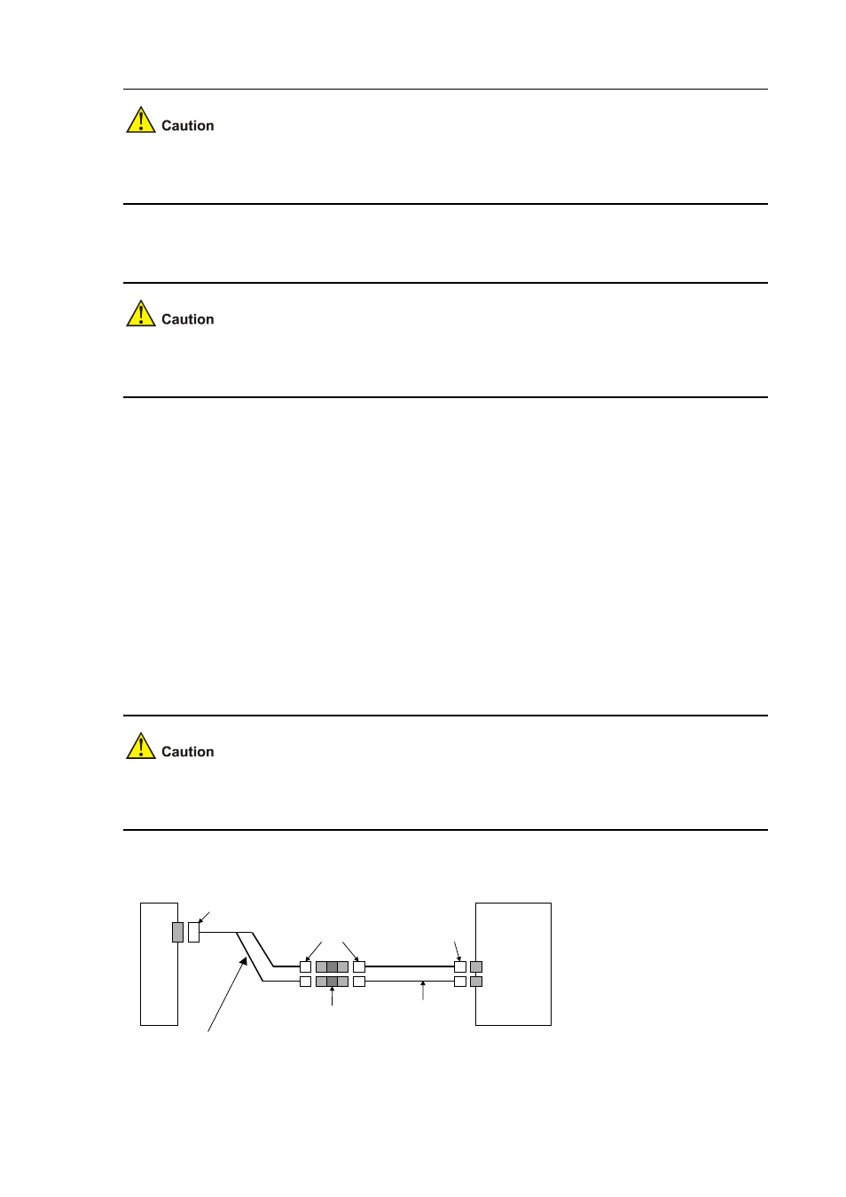
Figure 2-20 Extend an E1 75-ohm unbalanced coaxial cable
Router
Network
devices
such as DDN
DB-15
Coaxial connector
BNC
BNC
75-ohm non-balanced coaxial cable
75-ohm E1 trunk cable