Connecting the interface cable – H3C Technologies H3C MSR 50 User Manual
Page 183
Advertising
3-79
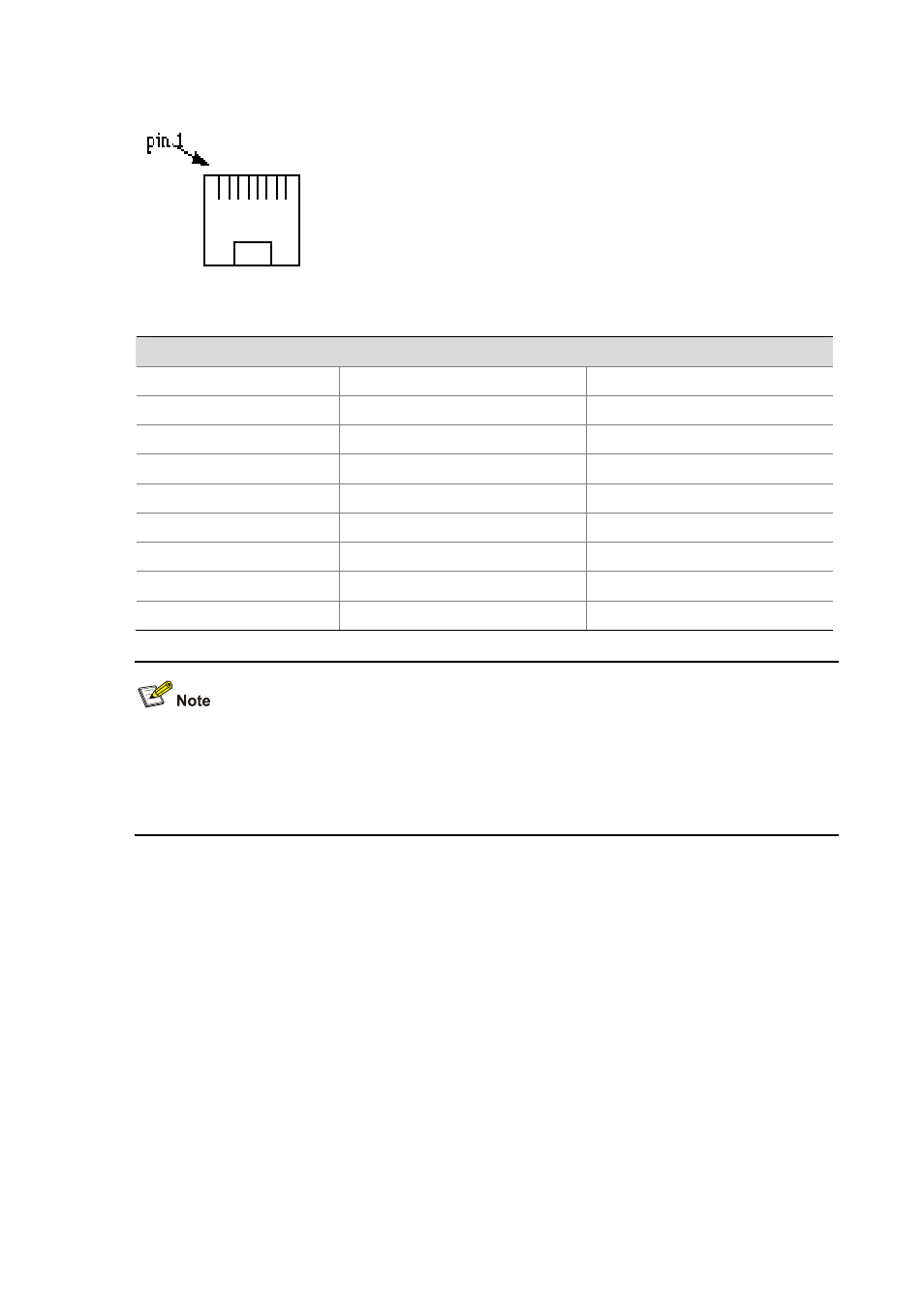
Figure 3-97 Sequence of RJ-45 pins
Table 3-67 Pinouts of E&M interface cable (Bell V 4-wire)
E&M interface
RJ-45 Pin
Signal
Signal direction
1 —
—
2 E
IN
3 RING0 IN
4 RING1 OUT
5 TIP1
OUT
6 TIP0
IN
7 M
OUT
8 SG
Ground
Because the 2E&M and 4E&M modules cannot determine the interface types (Bell I/II/III/V), cable types
(2-wire or 4-wire), and pinouts (E/M/Tx/Rx) of the peer switch, you must prepare the interface cables of
the 2E&M and 4E&M modules according to the on-site conditions. To ensure the EMC of the router,
install a ferrite core near the connector of the E&M module interface cable at the router side.
Connecting the interface cable
Advertising
This manual is related to the following products: