Interface leds, Interface cable, Connecting the interface cable – H3C Technologies H3C MSR 50 User Manual
Page 59
2-39
Attribute
DSIC-1SHDSL-8W
Interface standard
ITU-T G991.2 ANNEX A, ANNEX B, ANNEX F, ANNEX G
ITU-T G994.1 handshaking
Interface rate
z
5.69 Mbps (1 pair mode)
z
11.38 Mbps (2 pair mode)
z
17.07 Mbps (3 pair mode)
z
22.76 Mbps (4 pair mode)
Cable
Telephone cable with ferrite core (one RJ-45 connector converts to two
RJ-11 connectors.)
Operation mode
z
ATM
z
EFM
Supported services
G.SHDSL over the regular telephone line
Interface LEDs
The following figure illustrates the DSIC-1SHDSL-8W panel.
Figure 2-50 DSIC-1SHDSL-8W panel
The following table describes the LEDs on the module panel.
Table 2-29 LEDs on the DSIC-1SHDSL-8W panel
LED
Description
LINK/ACT (P0-P3)
z
ON means a carrier signal is received.
z
OFF means no carrier signals is received.
z
Fast blinking means data is being received or/and transmitted.
z
Slow blinking means the module is negotiating rates.
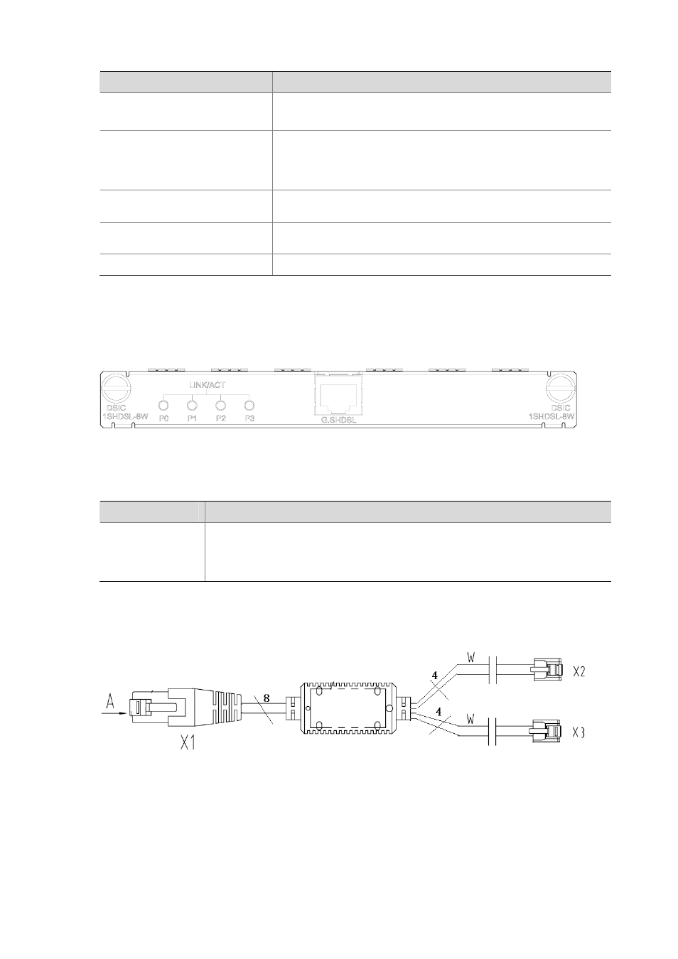
Interface cable
Figure 2-51 DSIC-1SHDSL-8W cable
Connecting the interface cable
Follow these steps to connect the DSIC-1SHDSL-8W cable:
Step1 Connect the RJ-45 connector of the cable to the G. SHDSL interface of the DSIC-1SHDSL-8W.
Step2 Connect the other end of the cable to its corresponding device.