H3C Technologies H3C MSR 50 User Manual
Page 80
2-60
z
Connect the BNC connector of the cable to the coaxial connector and the other end of the coaxial
connector to the remote network equipment through a 75-ohm E1 trunk cable, if cable extension is
needed.
The wire marked TX in the E1 cable should be connected to the peer wire marked RX and the wire
marked RX should be connected to the peer wire marked TX.
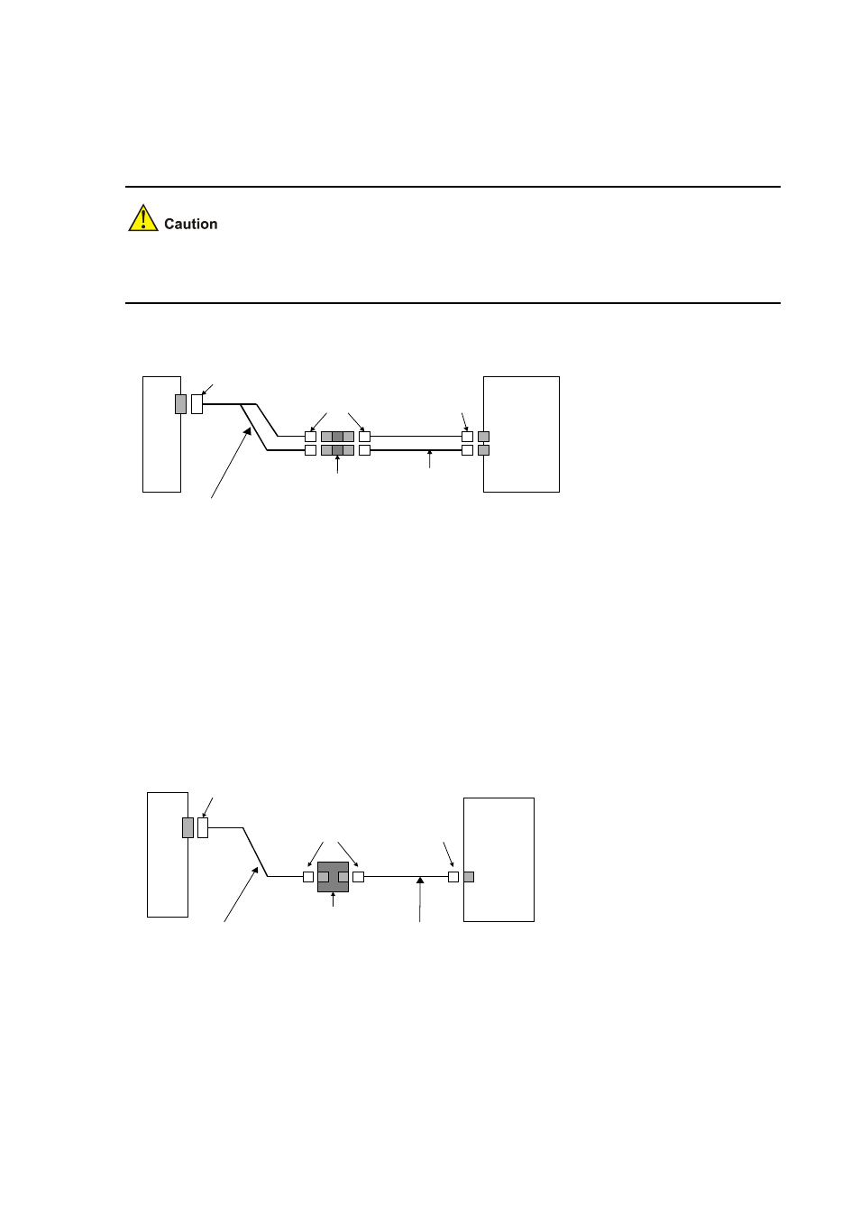
Figure 2-75 Extending an E1 75-ohm unbalanced coaxial cable
Router
Network
devices
such as DDN
DB -15
Coaxial connector
BNC
BNC
75-ohm non-balanced coaxial cable
75-ohm E1 trunk cable
If the remote device has 120-ohm interface, it is needed to use a 75-ohm-to-120-ohm adapter or use a
120-ohm cable.
2) When the E1 cable is a 120-ohm balanced twisted pair cable:
z
Connect the RJ-45 connector of the cable to the RJ-45 port of the remote equipment, if there is no
need to extend the E1 cable, or
z
Connect the RJ-45 connector of the cable to the network connector and the other end of the
network connector to the network equipment through a 120-ohm E1 trunk cable, if cable extension
is needed.
Figure 2-76 Extending an E1 120-ohm balanced twisted pair cable
Router
Network
devices such
as DDN
D B-15
Network interface connector
R J-45
R J-45
120-ohm balanced tw isted pair
120-ohm E1 trunk cable
Step4 Check the status of LINK LED on the SIC-1VE1 panel: ON means the link is connected and OFF
means the link is not connected. In the latter case, check the line.