Internal dip switches – H3C Technologies H3C MSR 50 User Manual
Page 140
3-36
Internal DIP switches
MIM-1E1/MIM-2E1/MIM-4E1 and MIM-1E1-F/MIM-2E1-F/MIM-4E1-F modules provide internal DIP
switches, and the setting of DIP switches decides the interface impedance and grounding mode.
Table 3-32 Correlation between DIP switches of MIM-1E1/MIM-2E1/MIM-4E1 and
MIM-1E1-F/MIM-2E1-F/MIM-4E1-F modules and E1 interface
Module
MIM-1E1/1E1-F
MIM-2E1/2E1-F
MIM-4E1/4E1-F
DIP
switch
S1
S1 S2 S1 S3 S4 S5
E1 interface
Interface
0
Interface 0
Interface 1
Interface 0
Interface 1
Interface 2
Interface 3
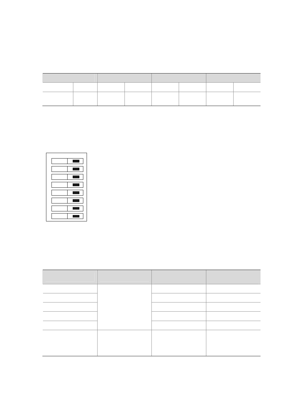
By default, all the DIP switches for MIM-1E1/MIM-2E1/MIM-4E1 and
MIM-1E1-F/MIM-2E1-F/MIM-4E1-F modules are set to ON, as illustrated in the following figure:
Figure 3-41 Default setting of DIP switches for MIM-1E1/MIM-2E1/MIM-4E1 and
MIM-1E1-F/MIM-2E1-F/MIM-4E1-F modules
on
1
2
3
4
5
6
7
8
Description of DIP switch settings is given in the following table for MIM-1E1/MIM-2E1/MIM-4E1 and
MIM-1E1-F/MIM-2E1-F/MIM-4E1-F modules:
Table 3-33 Description of DIP switch settings of MIM-1E1/MIM-2E1/MIM-4E1 and
MIM-1E1-F/MIM-2E1-F/MIM-4E1-F modules
DIP
Description
Configuration of
75-ohm impedance
Configuration of
120-ohm impedance
1BIT ON
OFF
2BIT ON
OFF
3BIT ON
OFF
4BIT ON
OFF
5BIT
75-ohm/120-ohm
selection switch
ON OFF
6BIT
RxRing grounding mode
selection switch
OFF: RxRing is grounded
via capacitance.
ON: RxRing is grounded
directly.
—