Interface cable, Connecting the interface cable – H3C Technologies H3C MSR 50 User Manual
Page 170
3-66
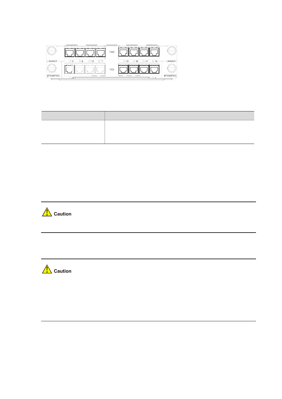
Figure 3-79 MIM-8FXS8FXO panel
The following table describes the LEDs on the MIM-8FXS8FXO panel.
Table 3-56 Description of the LEDs on the MIM-8FXS8FXO panel
LED
Description
LINK/ACT
z
OFF means no link is present.
z
Steady green means a link is present and a call connection is being
established.
z
Blinking yellow means a link is present and there is a call activity.
Interface Cable
The connection cables for MIM-8FXS8FXO are telephone cables with ferrite core. Both ends of the
cables are RJ-11 connectors. For cable pinouts, refer to Low-End and Mid-Range Series Routers
Cable Manual
.
Relevant cables are included in the standard shipment package of MIM-8FXS8FXO.
Connecting the interface cable
z
Before you connect a port, read its label carefully; a wrong connection can cause damages to the
interface module and even the device.
z
If outdoor cabling is involved, consider to install a special lightning arrester at the input end of the
interface cable for better lightning protection.
z
When connecting an interface cable, connect the end with ferrite core to the router for EMC sake.
If the interface module is properly installed, follow these steps to connect the cable:
Step1 Insert the ferrite core end of the cable into the to-be-connected RJ-11 port on the interface module.
Step2 Connect the other end of the cable as follows: