Interface cable, Connecting the interface cable – H3C Technologies H3C MSR 50 User Manual
Page 156
3-52
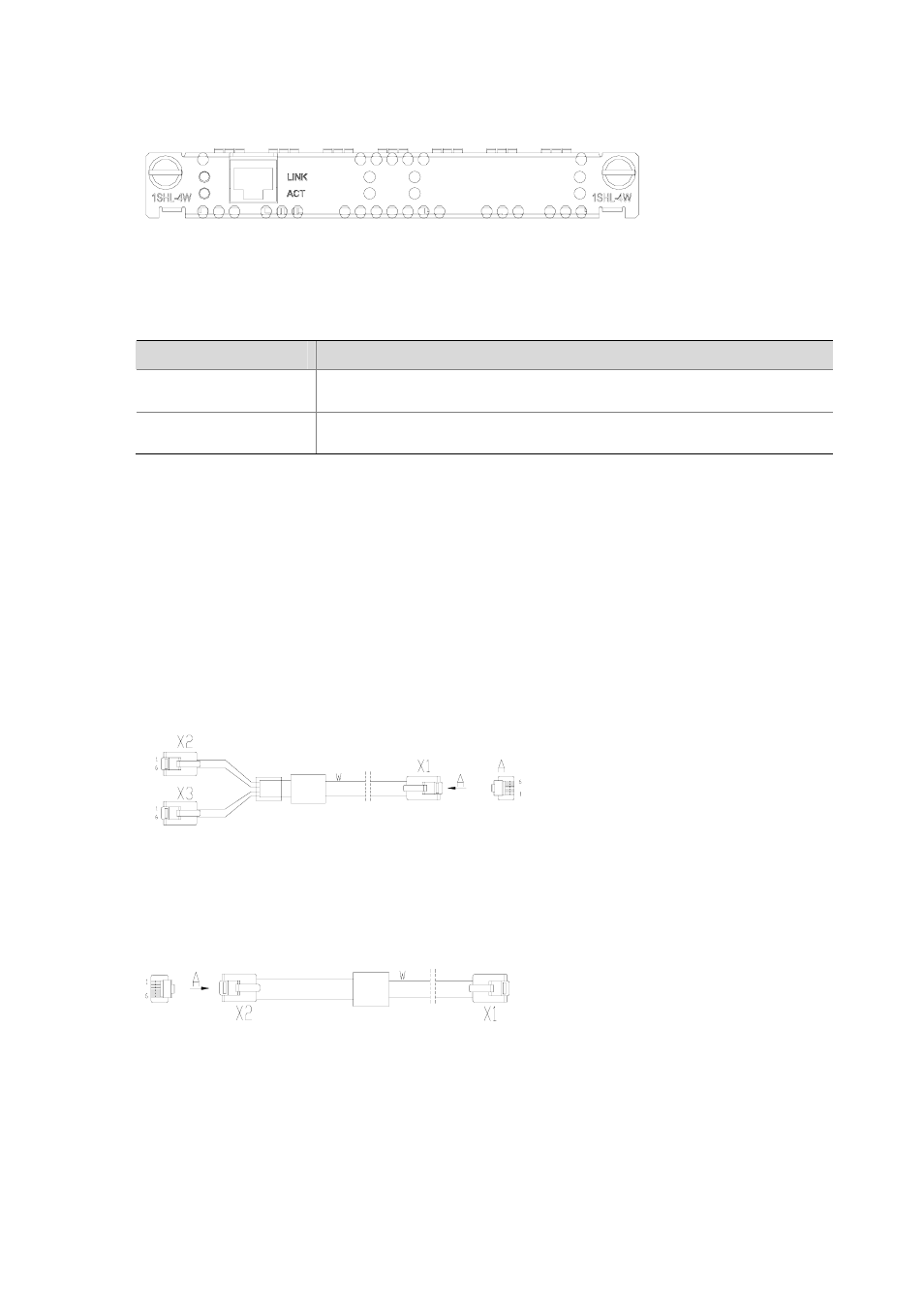
Figure 3-58 MIM-1SHL-4W panel
The following table describes the LEDs on the MIM-1SHL-4W panel.
Table 3-45 LEDs on the MIM-1SHL-4W panel
LED
Description
LINK
z
OFF means no link is present.
z
ON means a link is present.
ACT
z
OFF means no data is being transmitted or received.
z
Blinking means data is being received or transmitted.
Interface cable
MIM-1SHL-4W uses a tailor-made 4-wire telephone cable of type “Y” or “I”. You can select the type as
needed.
z
As shown in the following figure, on one end of the type “Y” G.SHDSL cable there is one RJ-11
connector (X1), which is used to connect the MIM-1SHL-4W module; on the other end there are
two RJ-11 connectors (X2 and X3), which can connect two 2-wire telephone lines. Pins 3 and 4 of
X1 are connected with pins 3 and 4 of X2, and pins 2 and 5 of X1 are connected with pins 3 and 4
of X3.
Figure 3-59 Type “Y” cable
z
As shown in the following figure, on both ends of the “I” type G.SHDSL cable there is an RJ-11
connector. The “I” type G.SHDSL cable can connect one 4-wire telephone cable.
Figure 3-60 “I” type cable
Connecting the interface cable
z
When using the “Y” cable, connect the X1 end of the cable to the interface on MIM-1SHL-4W and
connect the other two ends (X2, X3) to DSLAM through PSTN.
z
When using the “I” cable, connect one end of the cable to the interface on MIM-1SHL-4W and the
other end to DSLAM through PSTN.