Interface cable, Connecting the interface cable – H3C Technologies H3C MSR 50 User Manual
Page 82
2-62
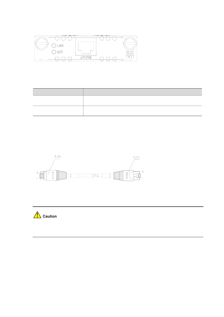
Figure 2-77 SIC-1VT1 panel
The following table describes the LEDs on the SIC-1VT1 panel.
Table 2-48 Description of SIC-1VT1 LED
LED
Description
LINK
z
ON means carrier signal is received;
z
OFF means no carrier signal is received.
ACT
z
OFF: No data is being received and transmitted;
z
Blinking: Data is being received and transmitted.
Interface cable
The interface cable of SIC-1VT1 is a standard 100-ohm standard shielding cable. The connectors on
the two ends use RJ-45. The following figure illustrates this type of cable.
Figure 2-78 T1 cable
For the pinouts of T1 cables, see Low-End and Mid-Range Series Routers Cable Manual.
The corresponding cables are not included in the standard shipment package of SIC-1VT1. Please
order them together with SIC-1VT1. By default, they are not supplied.
Connecting the interface cable