Interface leds, Interface cable – H3C Technologies H3C MSR 50 User Manual
Page 38
2-18
DIP switch
Description
75-ohm impedance
120-ohm impedance
3BIT
ON
OFF
4BIT
ON
OFF
5BIT
ON
OFF
6BIT
Switch for RxRing
grounding mode options
OFF: RxRing grounding
via capacitor
ON: RxRing directly
grounding
—
7BIT
Switch for RxShield
grounding options
—
ON: RxShield grounding
OFF: RxShield
ungrounding
8BIT
Switch for RxShield
grounding options
—
OFF: RxShield grounding
via capacitor
ON: RxShield directly
grounding
z
When setting internal DIP switch, you are recommended to: turn ON all BITs from 1 to 8 when a
75-ohm cable is connected. Turn OFF all BITs from 1 to 8 when a 120-ohm cable is connected;
z
The default configuration of internal DIP switch is that all the 8 positions of the BIT switch are ON,
that is, the E1 interface impedance is 75-ohm.
Interface LEDs
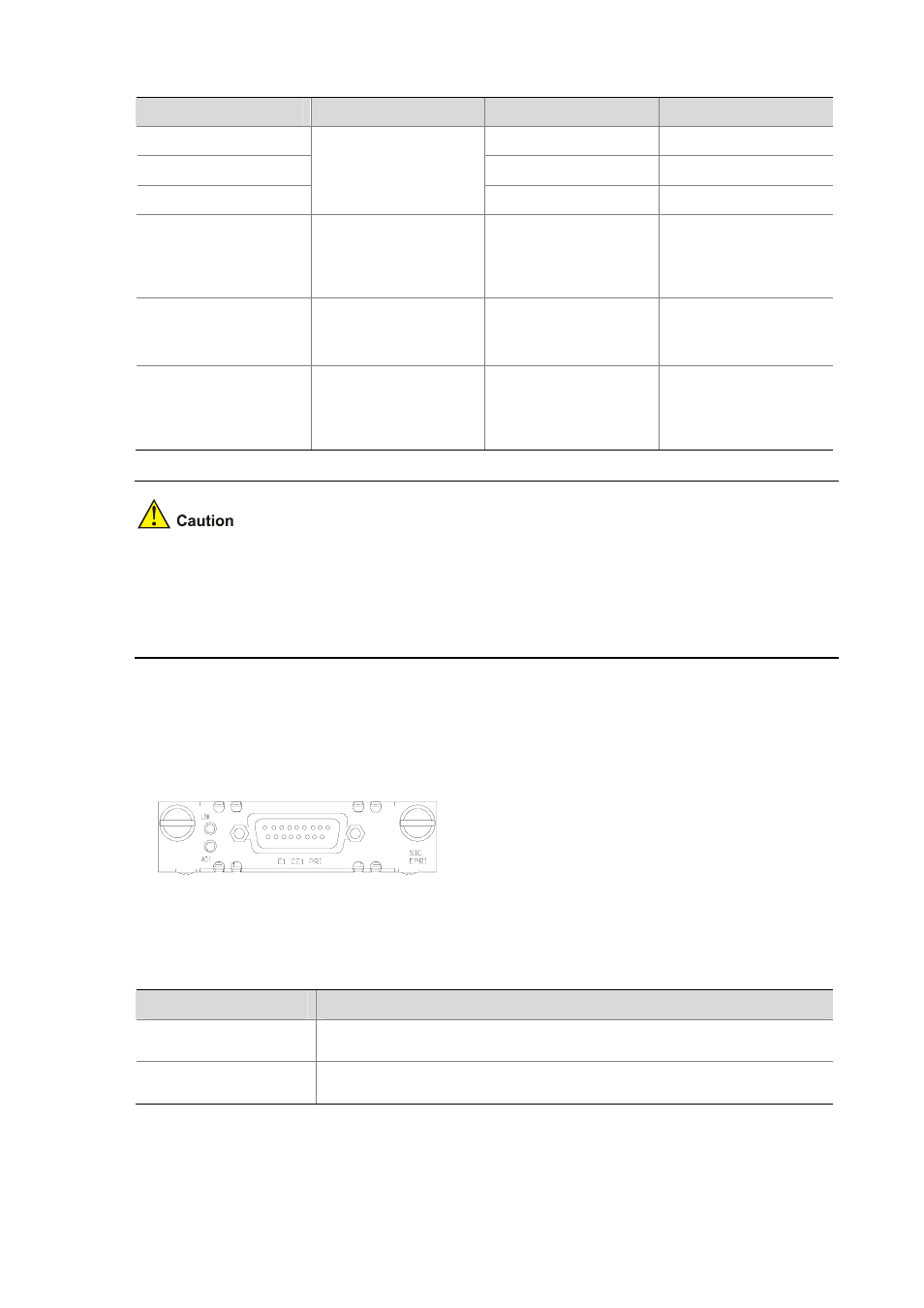
SIC-EPRI panel is shown in the following figure:
Figure 2-17 SIC-EPRI panel
The status description of the LEDs is given in the following table:
Table 2-17 Description of the LEDs on SIC-EPRI panel
LED
Description
LINK
z
ON means carrier signal has been received.
z
OFF means no carrier signal has been received.
ACT
z
OFF means no data is being transmitted or received.
z
Blinking means data is being received or/and transmitted.
Interface cable
Interface cables for SIC-EPRI are standard E1 G.703 cables. E1 G.703 cables have two types: 75-ohm
unbalanced coaxial cables and 120-ohm balanced twisted pair cables, shown as follows: