Interface leds, Interface optical fiber – H3C Technologies H3C MSR 50 User Manual
Page 222
4-27
For a long-haul fiber-optic interface, the transmission distance must be longer than 25 km (15.5 in.) to
allow the receiver to work. In case of closer distances, insert an optical attenuator to reduce the input
optical power.
Interface LEDs
The following figure illustrates the FIC-1CPOS(E) panel:
Figure 4-28 FIC-1CPOS(E) panel
The following figure illustrates the FIC-1CPOS(T) panel:
Figure 4-29 FIC-1CPOS(T) panel
The following table describes the LEDs on the FIC-1CPOS(E) and FIC-1CPOS(T) panels.
Table 4-26 LEDs on the FIC-1CPOS(E)/FIC-1CPOS(T) panel
LED
Description
LINK
z
OFF means no link is present;
z
ON means a link is present.
ACT
z
OFF means no data is being transmitted or received;
z
Blinking means data is being received or transmitted.
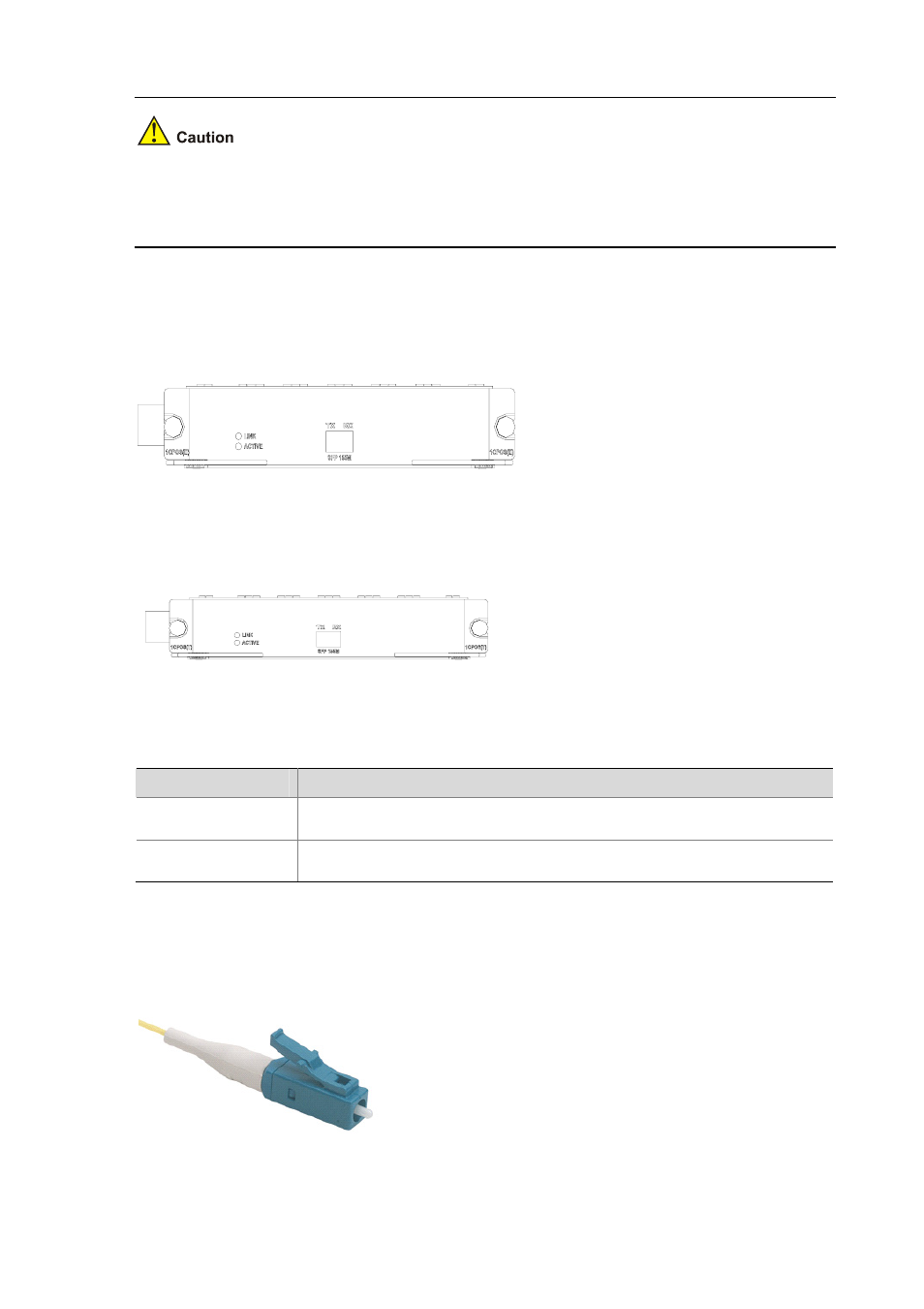
Interface optical fiber
The FIC-1CPOS can only be connected to an optical fiber cable with an LC-type fiber-optic connector.
Figure 4-30 LC-type fiber-optic connector