Interface cable, Connecting the interface cable – H3C Technologies H3C MSR 50 User Manual
Page 130
3-26
Figure 3-28 MIM-IMA-8T1 panel
LEDs on MIM-IMA-4T1 and MIM-IMA-8T1 panels have the same meanings, which are described in the
following table.
Table 3-25 Description of the LEDs on the MIM-IMA-4T1/MIM-IMA-8T1 panel
LED
Description
LINK
z
OFF means no link is present;
z
ON means a link is present.
ACT
z
OFF means no data is being transmitted or received.
z
ON means data is being transmitted or received.
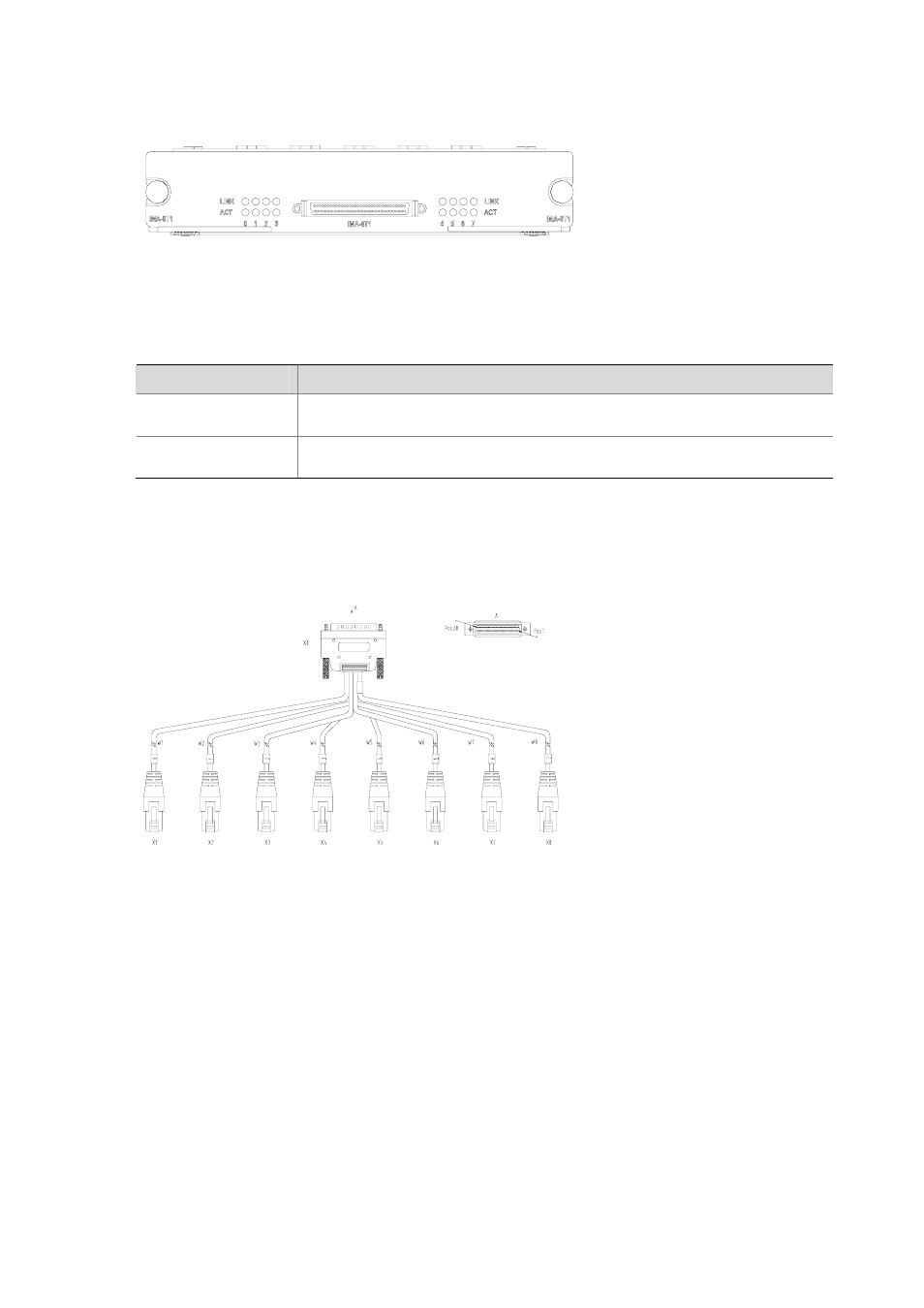
Interface cable
The following figure illustrates an 8T1 conversion cable.
Figure 3-29 8T1 conversion cable
The MIM-IMA-4T1 module provides four T1 ports and uses a 4T1 conversion cable. At one end of the
cable is a DB68 connector for connecting the router and at the other end are four RJ-45 connectors for
connecting other devices. MIM-IMA-8T1 provides eight T1 ports and uses an 8T1 conversion cable.
Connecting the interface cable
Follow these steps to connect MIM-IMA-4T1/MIM-IMA-8T1 interface cable.
Step1 Insert the DB68 connector at one end of the 4T1/8T1 conversion cable to the DB68 interface on the
MIM-IMA-4T1/ MIM-IMA-8T1 module.
Step2 Connect one RJ-45 connector at the other end of the cable to a peer device.
Step3 Power on the router. Check the status of the LINK LED on the module panel. OFF means the link is in
trouble and signal is out of synchronization. In this case, please check the link.