Interface cable – H3C Technologies H3C MSR 50 User Manual
Page 198
4-3
On the FIC-16FSW/FIC-16FSW-PoE/DFIC-24FSW/DFIC-24FSW-PoE panel, each port on the
network connector corresponds to one green LED. The following table describes the LEDs on the
FIC-16FSW/FIC-16FSW-PoE/DFIC-24FSW/DFIC-24FSW-PoE panel.
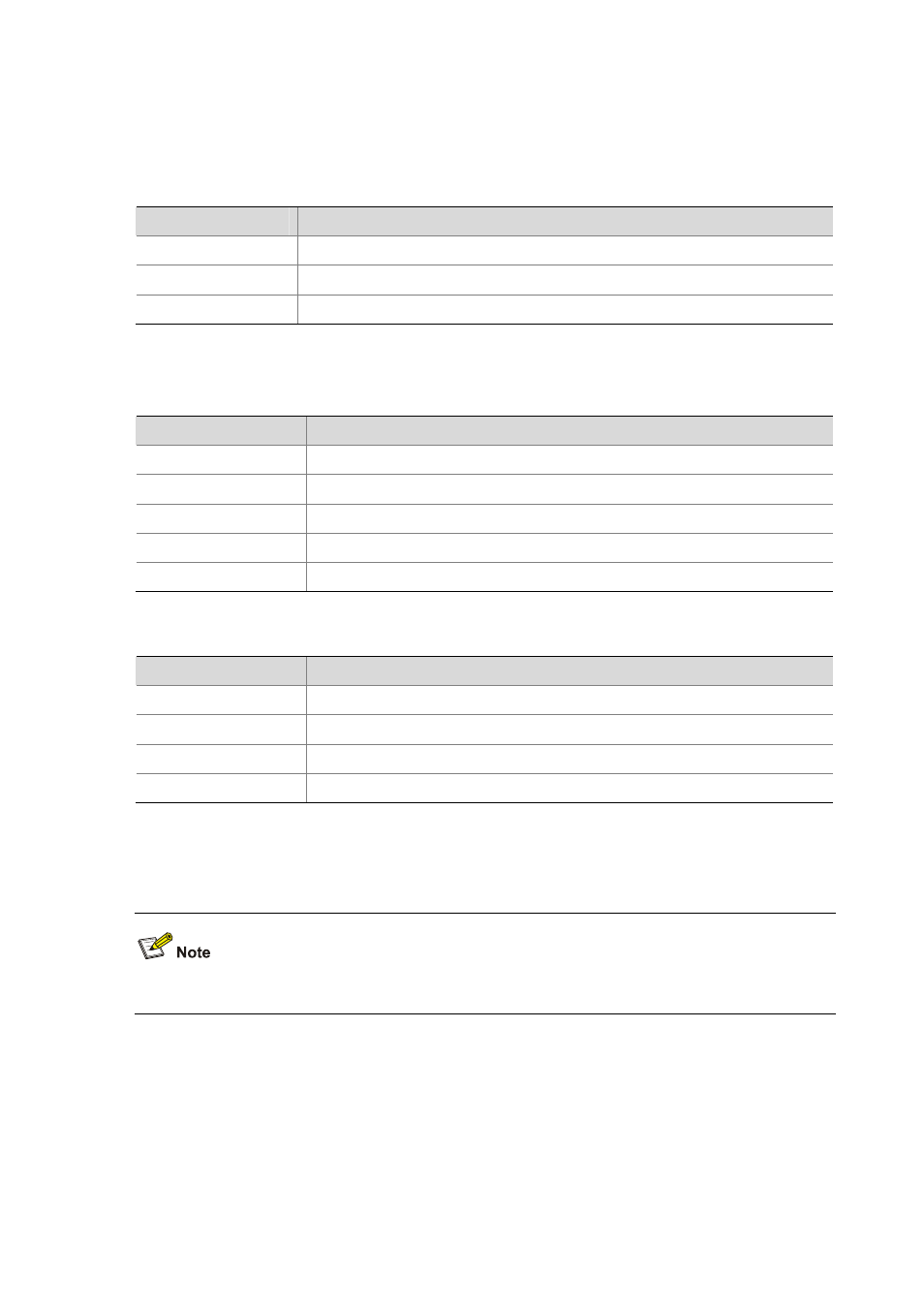
Table 4-2 LEDs on the FIC-16FSW/FIC-16FSW-PoE/DFIC-24FSW/DFIC-24FSW-PoE FE interface
LED
Description
Steady green
A link is present, but no data is being transmitted and received.
OFF
No link is present.
Blinking green
A link is present and data is being transmitted and received (ACT).
The following table describes the LEDs on the GE port and SFP fiber interface:
Table 4-3 LEDs on the FIC-16FSW/FIC-16FSW-PoE/DFIC-24FSW/DFIC-24FSW-PoE GE interface
LED
Description
OFF
No link is present.
Steady green
A 1000 Mbps link is present, but no data is being transmitted and received.
Blinking green
A 1000 Mbps link is present and data is being transmitted and received (ACT).
Steady yellow
A 100 Mbps link is present, but no data is being transmitted and received.
Blinking yellow
A 100 Mbps link is present and data is being transmitted and received (ACT).
Table 4-4 LEDs on the FIC-16FSW/FIC-16FSW-PoE/DFIC-24FSW/DFIC-24FSW-PoE fiber interface
LED
Description
OFF
No link is present.
Steady green
A link is present, but no data is being transmitted and received.
Blinking green
A link is present and data is being transmitted and received (ACT).
Steady yellow
Error prompt
In addition, there is a POE LED on each module, which is provided for the corresponding boards
(FIC-16FSW-PoE and DFIC-24FSW-PoE) with the PoE function.
The two GE interfaces on the DFIC-24FSW-PoE do not support the PoE function.
Interface cable
Typically, category-5 twisted pair cable is adopted to connect the 10BASE-T /100BASE-TX Ethernet
interface to the Ethernet, as shown in the following figure: