Connecting the interface optic fiber – H3C Technologies H3C MSR 50 User Manual
Page 199
4-4
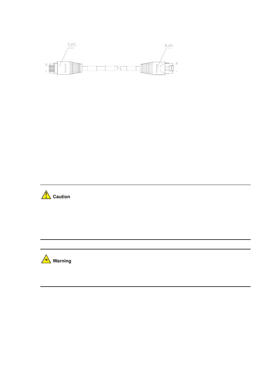
Figure 4-3 Ethernet cable
Ethernet cables fall into two categories: straight-through cables and crossover cables:
z
Straight-through cable: The sequences of the twisted pairs crimped by RJ-45 connectors at both
ends are the same. It is used for the connection between a terminal device (e.g., PC and router)
and a Hub/LAN switch. The cables delivered with the router are straight-through cables.
z
Crossover cable: The sequences of the twisted pairs crimped by RJ-45 connectors at both ends
are different. It is used for the connection between terminal devices (e.g., PC and router). In
addition, it can be made by the user.
For the pinouts of straight-through Ethernet cable and crossover Ethernet cable, see Low-End and
Mid-Range Series Routers Cable Manual.
Connecting the interface optic fiber
1) Connecting Ethernet fiber interface cable
When connecting the optical fiber, observe the following:
z
Do not over-bend the optical fiber. Its curvature radius must be no less than 10 cm (3.9 in).
z
Make sure that the Tx and Rx ends are correctly connected.
z
Make sure that the fiber ends are clean.
Laser danger: Invisible laser radiation may be emitted from the fiber-optic ports which are connected to
lasers. To protect your eyes against radiation harm, never stare into an open fiber-optic port.
Step1 Insert the SFP optical module into its corresponding slot.
Step2 Locate the Rx and Tx ports of the GE interface. Connect them to another device with two optical fibers:
Rx to Tx and Tx to Rx.
Step3 Check the status of LINK LED on the GE interface: ON means the link is connected and OFF means
the link is not connected. In the latter case, check the line.
2) Connecting Ethernet electrical cable