Network 2 (5260 only) interface pin assignments, Supervisory port pin assignments – Verilink WANsuite 5230 (34-00304.F) Product Manual User Manual
Page 227
S p e c i f i c a t i o n s
A-9
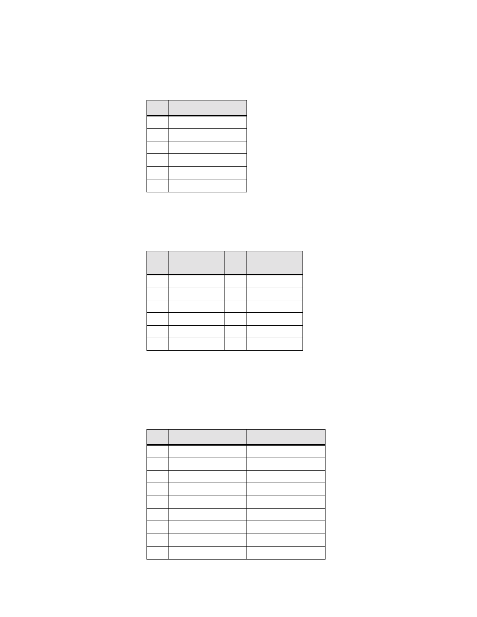
Network 1 (5260) and Network (5230) Interface Pin
Assignments
The
NET 1
and
NET
physical interfaces are both standard RJ-48C, eight -pin
modular jacks. The table below displays the pinout assignments for both.
Network 2 (5260 Only) Interface Pin Assignments
The
NET 2
physical interface is a standard RJ-48C, eight-pin modular jack.
The table below displays the pinout assignments.
*Selected by H7 Option Strap
Supervisory Port Pin Assignments
The
SUPERVISORY PORT
interface is a standard DB-9, nine-pin modular
jack. The table below displays the pinout assignments.
Pin
E1 NET Interface
1
Data In
2
Data In
3, 6
Not used
4
Data Out
5
Data Out
7, 8
Not Used
Pin
E1 NET
Interface
Pin
DSX
Interface*
1
Data Out
1
Data In
2
Data Out
2
Data In
3, 6
Not used
3,6
Not Used
4
Data In
4
Data Out
5
Data In
5
Data Out
7, 8
Not Used
7,8
Not Used
Pin
DCE Mode
DTE Mode
1
DCD out
LL out
2
Rx Data out
Tx Data out
3
Tx Data in
Rx Data in
4
DTR in
DSR in
5
Signal Ground
Signal Ground
6
DSR out
DTR out
7
RTS in
CTS in
8
CTS out
RTS out
9
No connect
No connect