Dtr alarm control and status table, 10/100 ethernet screen (ip service details), Dtr alarm control and status table -14 – Verilink WANsuite 5230 (34-00304.F) Product Manual User Manual
Page 44: 10/100 ethernet screen (ip service details) -14
3-14
W A N s u i t e 5 2 6 0 / 5 2 3 0
DTR Alarm Control and Status Table
In addition to the configurable fields, the Serial screens display a table that
lets you set the Data Terminal Ready (DTR) Alarm Control parameters and
view the current DTR Alarm Status.
Choices for DTR Alarm Control are “Enable” and “Disable.” The default
setting is “Disable.” Setting DTR Alarm Control to “Enable” allows the unit
to go into alarm on a loss of DTR, which occurs when the Serial port detects
that the DTR signal is low. The DTR Status field indicates the current state of
the DTR alarm.
The Serial screens provide the user-activated buttons described in the
following table:
To make changes to any Serial port parameter, simply set the parameter to the
desired selection and click the “Submit” button.
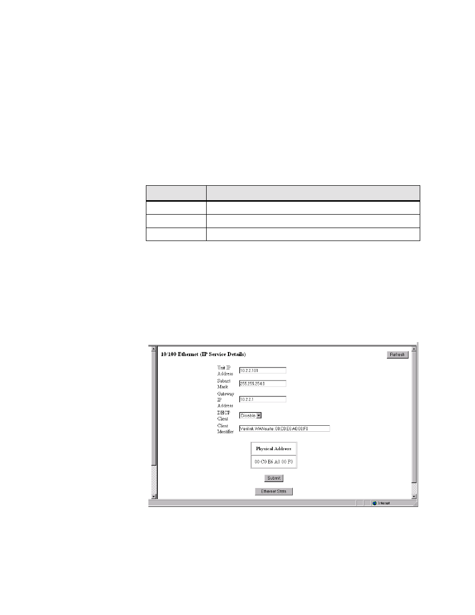
10/100 Ethernet Screen (IP Service Details)
The 10/100 Ethernet (IP Service Details) screen (Figure 3.9) lets you
configure the IP parameters described below.
Figure 3.9
10/100 Ethernet (IP Service Details) Screen
Unit IP Address
A unique network address assigned to this unit.
Subnet Mask
Defines the network portion of the unit’s IP address.
Button
Function
Submit
Sets any values that have been changed.
Serial 1 Services
Displays the Services screen for Serial #1 interface.
Refresh
Refreshes data on the current page.