Fail safe mode, Rack card dip switch – Wavetronix SmartSensor Advance Extended Range (SS-200E) - User Guide User Manual
Page 133
132
CHAPTER 12 • PROGRAMMING CONTACT CLOSURES
two channels. If you would like to use more than two channels, you will need a 4-channel
card or you will need to daisy-chain rack cards together.
Note
It is recommended to select a channel order using the sensor configuration software,
rather than using step 2 of the rack card.
Fail Safe Mode
If the rack card is in fail-safe mode (constant call on all channels), you can check connectiv-
ity by connecting an RS-485 to RS-232 converter (Click 304) to the T-bus expansion slot on
the traffic cabinet assembly. The sensor’s RS-232 port is completely independent and may
become unreliable at communication lengths greater than 200 ft. (61 m).
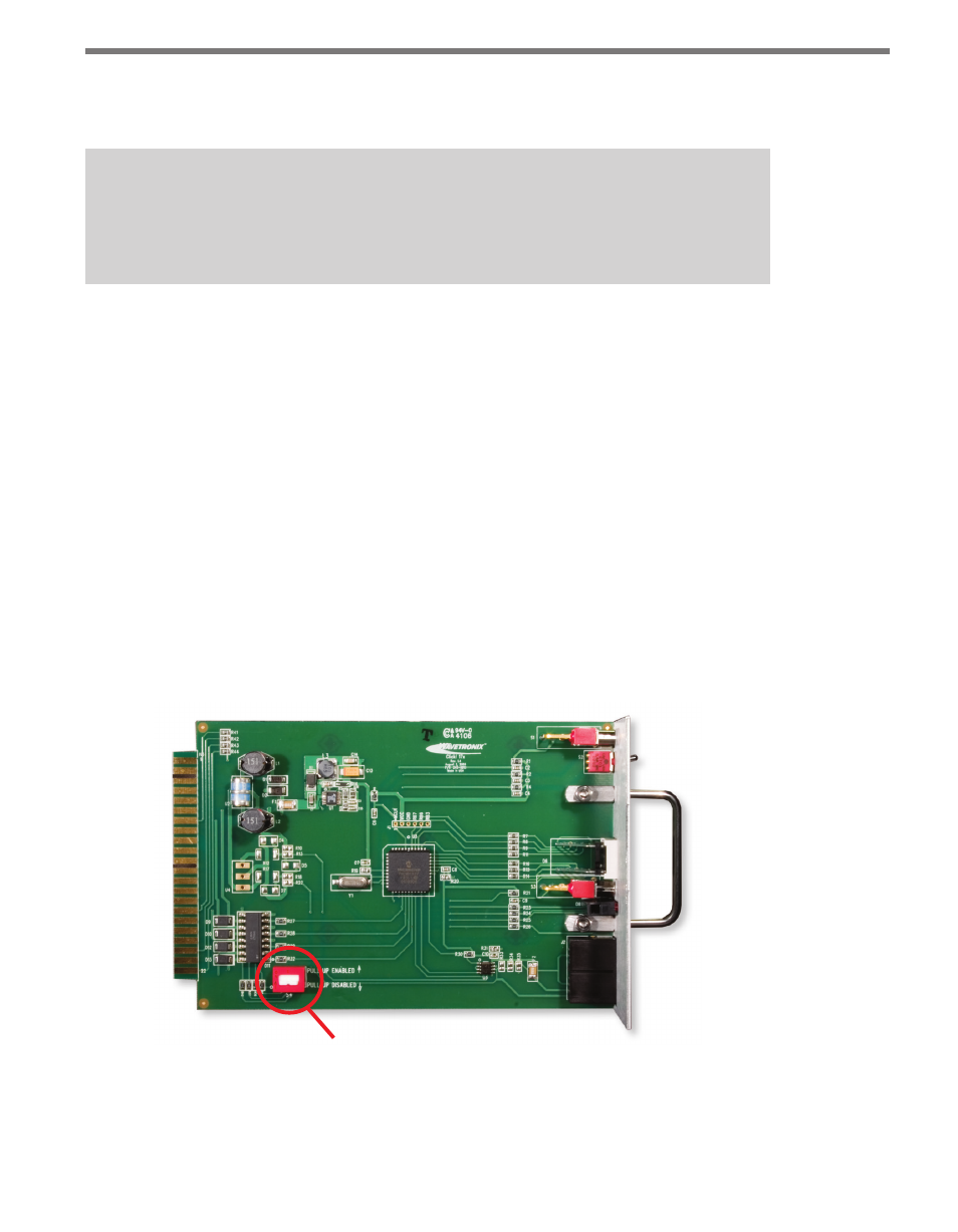
Rack Card Dip Switch
If you are seeing calls on the rack card LEDs, but do NOT see them registering in your
controller, you may need to disable the rack card’s pull-up circuitry. To do so, use the dip
switch on the rack card circuit board. If pull-up is enabled, the rack card will pull its back-
plane contact pins high when the contact is open. However, if pull-up is disabled, the rack
itself will need to pull the contact pins high when the contact is open. In either case, when a
contact closure occurs, it is the responsibility of the rack card to pull the associated contact
pin low (see Figure 12.3).
Rack card DIP switch
Figure 12.3 – Dip Switch on the Click 172/174 Cards
Once the contact closure card is configured, the controller’s detector inputs must be set up
and then assigned to the correct phases of the intersection.