Wavetronix SmartSensor Advance Extended Range (SS-200E) - User Guide User Manual
Page 145
144
APPENDIX
Height (ft/m)
Off
set (
ft / m)
17/5.2
20 /6.1
25/7.6
30/9.1
35/10.7
40 /12.2
Y
Roll Y
Roll Y
Roll Y
Roll Y
Roll Y
Roll
0/0
40
0°
45
0°
55
0°
60
0°
70
0°
75
0°
5 /1.5
45
19°
45
16°
60
13°
65
12°
70
10°
80
9°
10/3
50
35° 50
31°
60
25° 65
22° 75
19°
80
17°
15/4.6
50
47° 55
42° 65
36° 70
32° 75
28° 80
24°
20/6.1
55
56° 55
51°
65
44° 75
39° 80
35° 90
32°
25/7.6
60
62° 65
57°
65
51°
75
46° 80
41°
90
38°
30/9.1
65
67°
70
63° 75
56° 80
51°
85
47° 95
43°
35/10.7
70
71°
75
67°
85
61°
85
56° 95
52° 95
48°
40/12.2
80
74°
90
71°
90
65° 95
60° 95
57°
100 52°
45/13.7
95
76°
100 73°
100 68° 100 64° 100 59° 105 56°
50/15.2
100 78° 100 76°
105 71°
110
66° 115
62° 120 59°
Table D.1 – Target Roll Angle
Note
If you would like to narrow the coverage of the sensor at far ranges, consider reducing
the target location by about 25%. For example, if your current target location is 40 ft,
you could reduce it to around 30 ft. Or, if you target location is 120 feet, you could re-
duce it to around 90 feet. This can be helpful if you have significant roadside clutter.
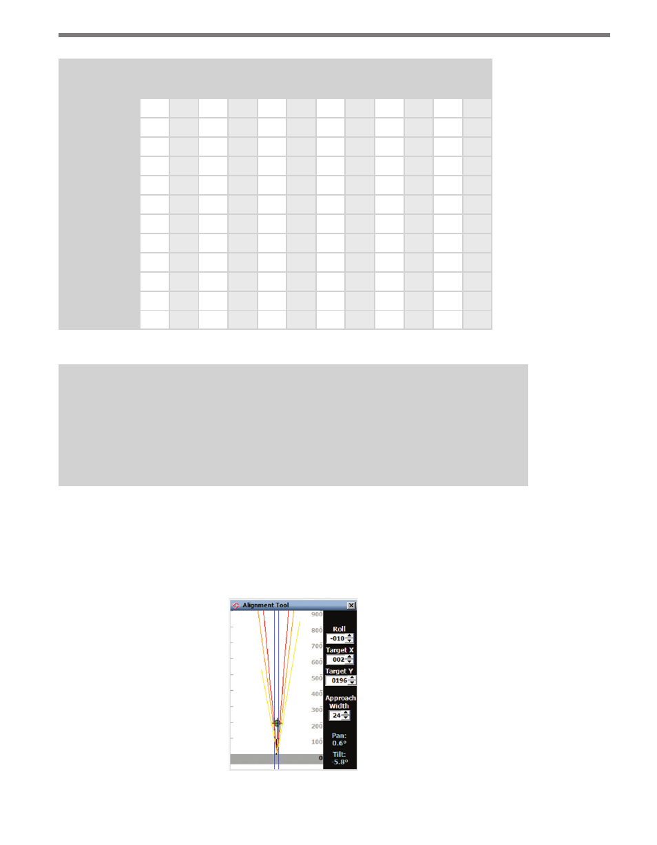
The information in this table was derived using the Alignment Tool in the configuration
software (see Figure D.1). You can use this tool to see the effects of a sensor that is not
properly aligned. The goal is to have the red contour (half power level contour) line up and
down the roadway over the lanes of interest. Chapter 8 of this document gives information
related to the use of the alignment tool.
Figure D.1 – Alignment Tool