Wavetronix SmartSensor Advance Extended Range (SS-200E) - User Guide User Manual
Page 18
CHAPTER 1 • INSTALLING THE SMARTSENSOR ADVANCE
17
Main Shaft
Mount Head
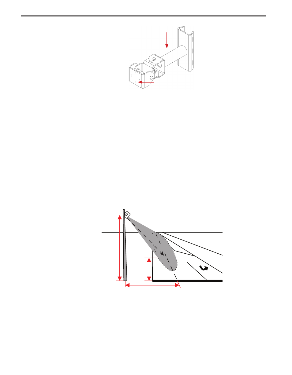
Figure 1.1 – Mount Bracket
Before attaching the mount bracket to the pole, first make sure that your cables are long
enough to support the sensor height and the distance from the sensor to the cabinet.
Follow the steps below to correctly attach the mount to the pole (see Figure 1.2):
1 Insert the stainless steel straps through the slots in the mount bracket.
2 Position the mount so that it facilitates visual line-of-sight from the sensor to the tar-
get. You will need to have sufficient headroom behind the sensor to position your eye
behind the viewfinder alignment tool (the next section will go into detail about the
viewfinder alignment tool).
For a roadside installation (on a vertical pole) the mount's main shaft can be positioned
slightly ahead of perpendicular to the roadway; you can then look from the side of
the pole. For an overhead installation (on a mast arm) the mount's main shaft can be
positioned slightly above horizontal; you can then look over the pole (see Figure 1.2).
Height
Target
Distance
Offset (perpendicular)
Line
-of
-sight to target
X
Figure 1.2 – Pointing the Sensor
3 Tighten the strap screws (see Figure 1.3).