Channel led – Wavetronix SmartSensor Advance Extended Range (SS-200E) - User Guide User Manual
Page 97
96
CHAPTER 8 • VERIFY CHANNELS-ALERTS-ZONES
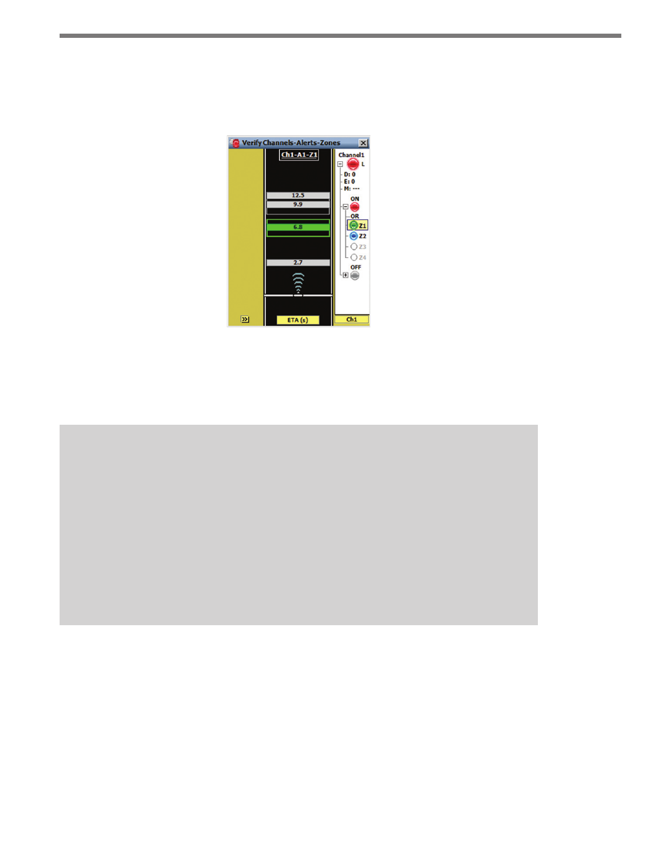
to the channel LED (see Figure 8.7). A channel’s delay, extend and max timer settings are
shown next to the D:, E: and M: labels under the channel LED. An alert identifier is dis-
played above each alert LED; the alert logic indicator (OR/AND) is located beneath each
alert LED. Only one alert can be expanded at a time.
Figure 8.7 – Individual Channel View (Latched Channel)
A zone label (Z1, Z2, Z3, Z4) is displayed to the right of each zone LED. If an alert has an
inverted zone, a logical NOT marker (solid black line) is displayed above the associated
zone label.
Tip
Click and hold on the alert LED to view the Alert Summary screen. The top of the Alert
Summary screen shows the channel that the alert belongs to. The rest of the screen
shows the logic applied to the alert, which zones are enabled and which zones are
inverted (if any).
Click and hold on the Zone LED to view the Zone Summary screen. The top of the
Zone Summary screen shows the channel and alert that the zone belongs to; the rest
of the screen shows the zone’s Range, Speed, ETA and Qualified Count settings for
the selected zone.
Channel LED
The channel LED is colored red whenever a channel’s output requirements are met (see the
Display Mode section). When a channel is selected, trackers are highlighted in light blue
if they meet any of the selected channel’s zone filters (see Figure 8.8). This form of tracker
highlighting helps you know which detections are affecting the channel’s output.