Understanding stp, Stp overview, Introduction – ATL Telecom R1-SW Ethernet Switch User Manual
Page 260
R1-SW24L2B User’s Manual
13-2
Understanding STP
This section introduces some basic information on STP (Spanning Tree Protocol) and RSTP
(Rapid STP).
STP Overview
Introduction
A network that has several paths for one destination is fault-tolerant. It is because packets can
be transmitted through other paths even if one of paths can not be used on the network. But,
loops might occur on the network. If a loop is occurs between two nodes, when packets are
broadcasted, the packet transmission is repeated infinitely. Because of the loop, the network can
be congested, then the network becomes instable.
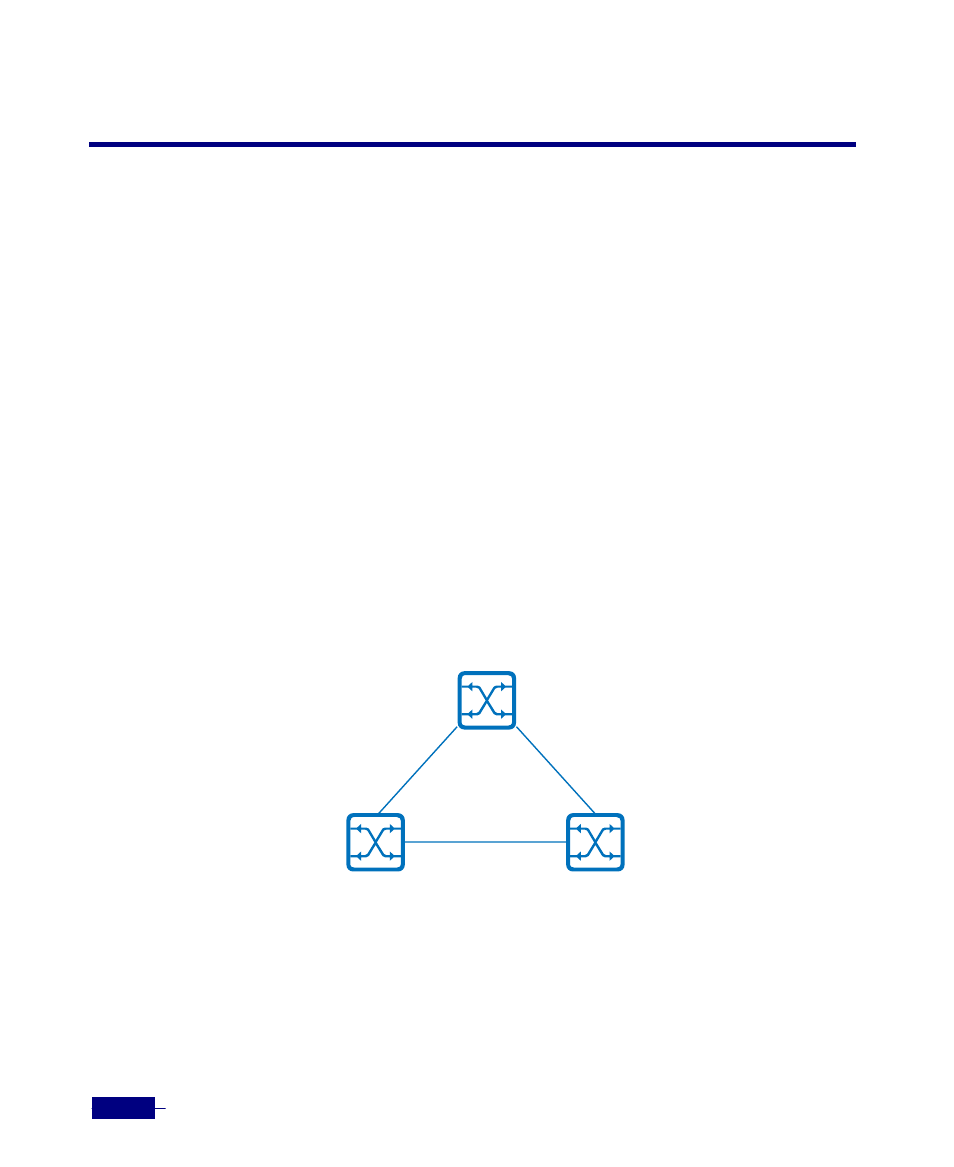
In the following network configuration, there are two paths from Switch A to Switch C. One of
the path is path 2 connected directly and the other path is path 1 and path 2 through Switch B.
A loop is formed in this network because multiple active paths exist between Switch A and
Switch C. In this network, end stations might receive duplicate messages. For example, if Switch
A broadcasts packets, Switch C broadcasts the received packets to Switch A, and Switch A
broadcast the packets again.
STP (Spanning Tree Protocol) prevents the loop on the network in which several paths are
existed. STP defines a tree with a root switch. When two interfaces on a switch are part of a loop,
the spanning-tree port priority and path cost settings determine which interface is put in the
forwarding state and which is put in the blocking state. Spanning tree forces redundant data
paths into a standby (blocked) state. Therefore, when traffic is processed, packets are only
transmitted through paths of non-blocking state.
Switch A
Switch B
Switch C
Path 1
Path 2
Path 3