Schematic for building an igbt tester, Schematic for building an igbt tester -15, Powermax – Hypertherm Powermax105 Service Manual User Manual
Page 153
Advertising
TroubleshooTing and sysTem TesTs
powermax
105 Service Manual
8-15
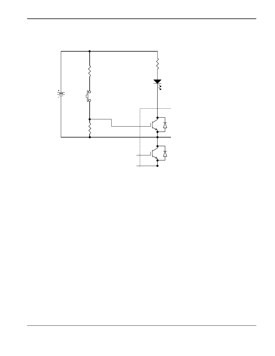
Legend
1. Collector 1 (C1)
2. Emitter 2 (E2)
3. Collector 2, Emitter 1 (C2,E1)
4. Gate 1 (G1)
5. Emitter 1 (E1)
6. Emitter 2 (E2)
7. Gate 2 (G2)
9 VDC
battery
R4
2.0K
009036
Normally open
(N.O.) push-button
switch
Yellow
Minigrabber
test clip 4
R1
3.01M
009464
Black
Minigrabber
test clip
Q1
150A
1400V
109125
R3
2.0K
009036
Red LED lamp
109092
Red Minigrabber
test clip
D1
1
2
3
5
6
7
Schematic for building an Igbt tester
Advertising
This manual is related to the following products: