Powermax, Troubleshooting and system tests 8-18, Service manual – Hypertherm Powermax105 Service Manual User Manual
Page 156
Advertising
TroubleshooTing and sysTem TesTs
8-18
powermax
105
Service Manual
J22
J21
J20
J19
J27
WORK
LEAD
J26
J25
+
_
+
_
RED
J18
ORG
J17
J32
J11
J28
TP7
TP9
TP8
W
R
B
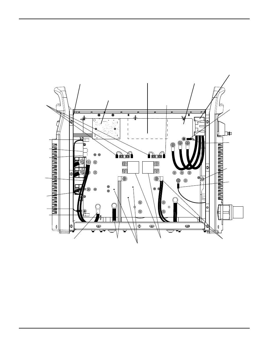
230-400 V CE, 380 V CCC/230-400 V CE power supply overview
Power switch (S1)
Power board
Flyback circuit
Control board
Digital signal processor
(DSP) board
Test points
Gate drive
connectors
J11 connector
J17 connector
J18 connector
J32 connector
PFC
Temperature
sensor
3uF Capacitors
Ground
Nozzle wires
Electrode wire
Transformer
wires
Damper
resistor wire
Damper
resistor wire
PFC Inductor
wires
AC Input
wires (3)
Output
inductor wires
Work lead
Advertising
This manual is related to the following products: