Powermax, Troubleshooting and system tests – Hypertherm Powermax105 Service Manual User Manual
Page 183
TroubleshooTing and sysTem TesTs
powermax
105 Service Manual
8-45
J22
J21
J20
J19
J27
WORK
LEAD
J26
+
_
+
_
TP7
TP9
TP8
W
R
B
J22
J21
J20
J19
J27
WORK
LEAD
J26
+
_
+
_
TP7
TP9
TP8
W
R
B
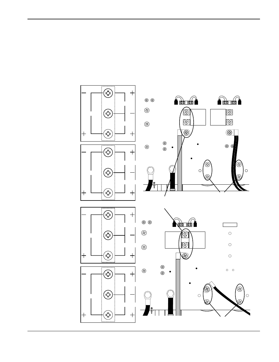
Voltage check
All voltages must be measured with the input power connected and the machine on.
Note: Wear proper personal protective equipment (PPE) before testing powered equipment. All values are ±15%.
• Check the inverter IGBT module voltages as described below.
• The voltage measured across the bulk capacitors (half the buss voltage or the smaller values above) should be
the same before and during torch operation.
375 VDC
Bulk capacitors
Inverter IGBT
module
425 VDC
280 VDC
265 VDC
750 VDC
850 VDC
560 VDC
530 VDC
375 VDC
425 VDC
280 VDC
265 VDC
200-480 V CSA,
380 V CCC/230-400 V
CE input
600 V CSA input
400 V CE input
380 V CCC input
Bulk capacitors