Powermax, Power supply component replacement – Hypertherm Powermax105 Service Manual User Manual
Page 223
Power SuPPly ComPonent rePlaCement
powermax
105 Service Manual
9-25
J22
J27
WORK
LEAD
J26
_
RED
J18
ORG
J17
J32
J11
B
R
J28
RED
J32
J18
Power board
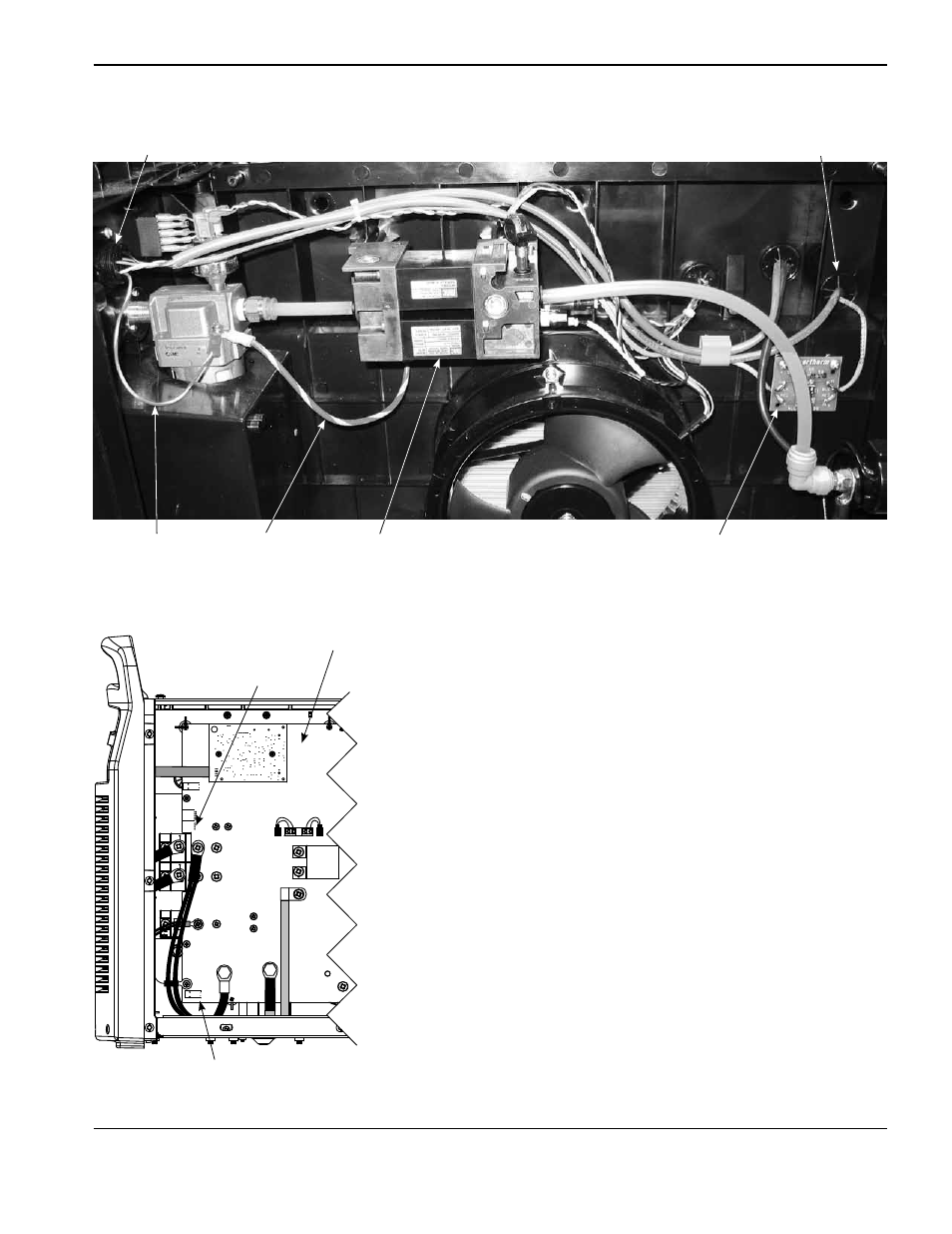
7. Route the large cable (from the CPC port) through the right
grommet and down the left side of the power board to the J18
connector.
8. Push the cable connector onto the power board connector. Be
sure to align the red wire in the cable connector with “RED” that is
printed on the power board.
9. Route the small cable (from the right side of the voltage divider
board) through the right grommet and down the left side of the
power board to the J32 connector.
10. Push the cable connector onto the power board connector. Be
sure to align the red wire in the cable connector with “RED” that is
printed on the power board.
CPC port
Solenoid valve
Right grommet
Voltage divider board
CPC port
ground wire
Center panel
ground wire