Powermax – Hypertherm Powermax105 Service Manual User Manual
Page 284
Power SuPPly ComPonent rePlaCement
9-86
powermax
105 Service Manual
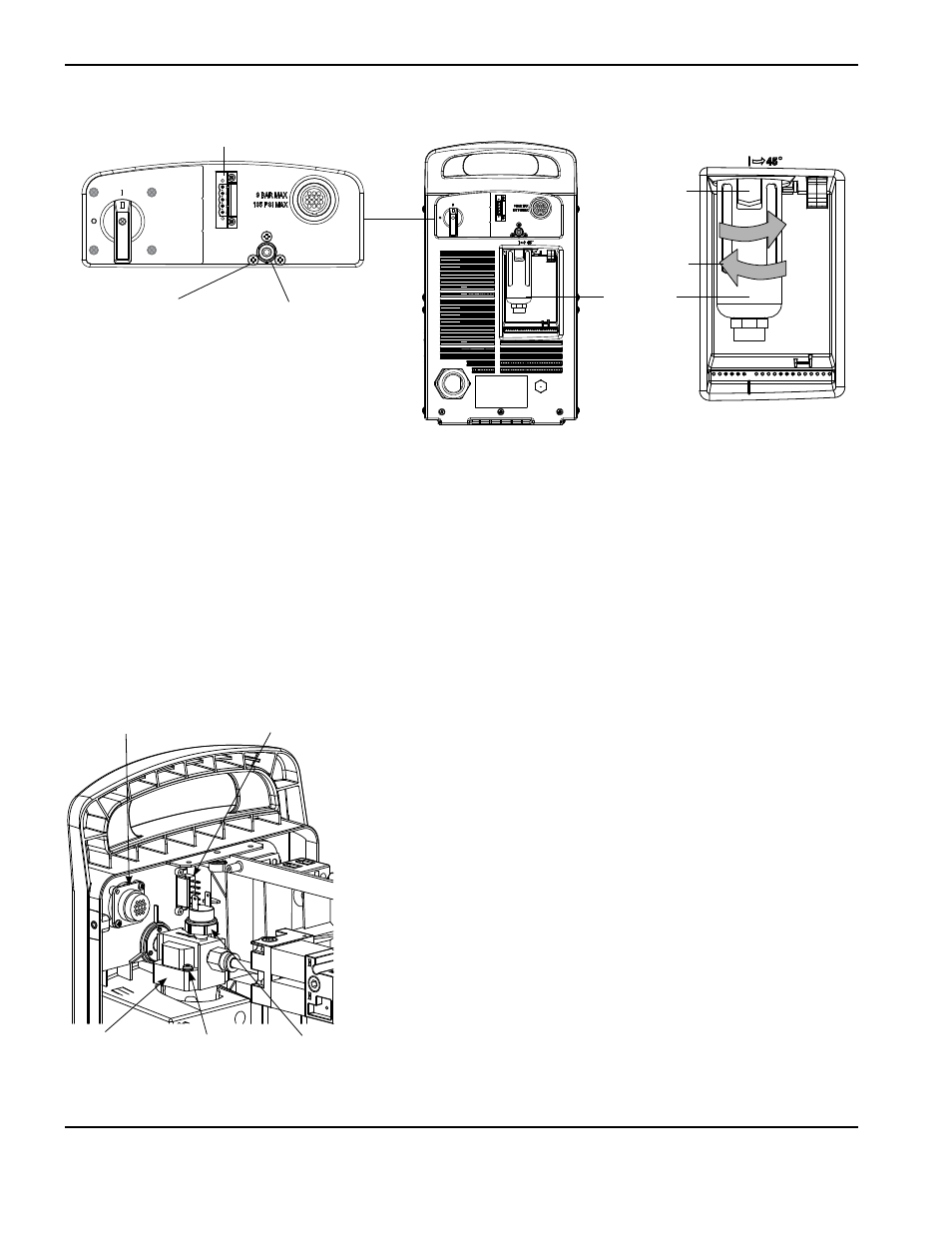
Optional RS485
connector
Optional CNC
interface connector
Pressure
switch
Ground wire
screw
Air filter
subassembly
Filter bowl
Gas fitting
Air filter
subassembly
mounting screws (3)
Thumb latch
Install
Optional RS485
connector
24. Position the air filter subassembly in the power supply and tighten the three mounting screws in the rear end panel
to 23 kg cm (20 in.-lbs).
25. Apply thread sealant to the gas fitting threads and tighten the gas fitting into the air filter subassembly.
26. Install the filter element and secure it to the bottom of the air filter subassembly by tightening (clockwise) the plastic
retaining nut.
27. Insert the filter bowl into the bottom of the air filter subassembly with the thumb latch positioned 45 degrees to the
right of center.
28. Vertically align and firmly push the filter bowl up until it is fully seated.
29. Rotate the filter bowl to the left until the thumb latch clicks into place.
30. If disconnected in an earlier step, connect the wires to the RS485
connector terminals, starting from the top, in the following order: red -
black - brown - white - green.
31. Connect the two wires to the pressure switch wire terminals (white wire
closest to the center panel).
32. If removed in an earlier step, secure the CNC interface connector to the
rear end panel by tightening the two mounting screws to 11.5 kg cm
(10 in.-lbs).
33. Secure the ground wire(s) to the air filter housing by tightening the
ground wire screw to 11.5 kg cm (10 in.-lbs).
Note: There will be two ground wires if the optional CNC interface
connector is installed in the rear panel.