Test 2 – dc power buss, Test 2 – dc power buss -44, Powermax – Hypertherm Powermax105 Service Manual User Manual
Page 182: Wr b
Advertising
TroubleshooTing and sysTem TesTs
8-44
powermax
105
Service Manual
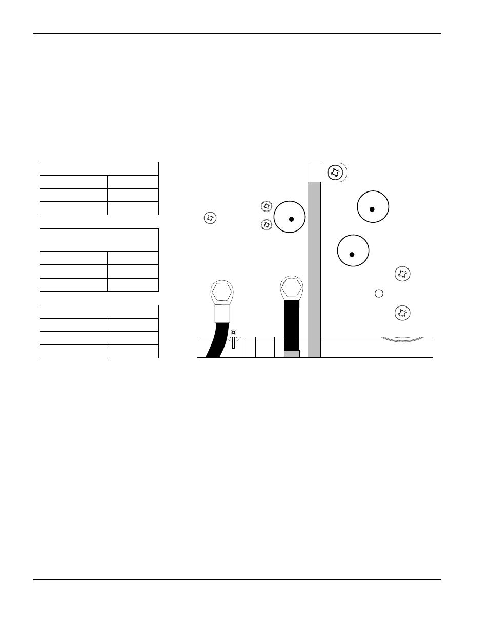
J27
WORK
LEAD
J26
+
_
TP7
TP9
TP8
W
R
B
test 2 – DC Power buss
Resistance check
Note: All resistance values must be taken with the power cord disconnected and all internal power supply wires
attached.
• Remove the mounting screws from the bulk capacitors and pull the caps away from the power board.
• Measure resistances described in the following tables.
200-600 V CSA
Test points
Value
TP 7 and 9
25 kΩ
TP 8 and 9
25 kΩ
230-400 V CE,
380 V CCC/230-400 V CE
Test points
Value
TP 7 and 9
25 kΩ
TP 8 and 9
25 kΩ
380 V CCC, 400 V CE
Test points
Value
TP 7 and 9
18 kΩ
TP 8 and 9
18 kΩ
• Replace the bulk capacitor mounting screws before power-up.
Advertising
This manual is related to the following products: