Powermax – Hypertherm Powermax105 Service Manual User Manual
Page 235
Power SuPPly ComPonent rePlaCement
powermax
105 Service Manual
9-37
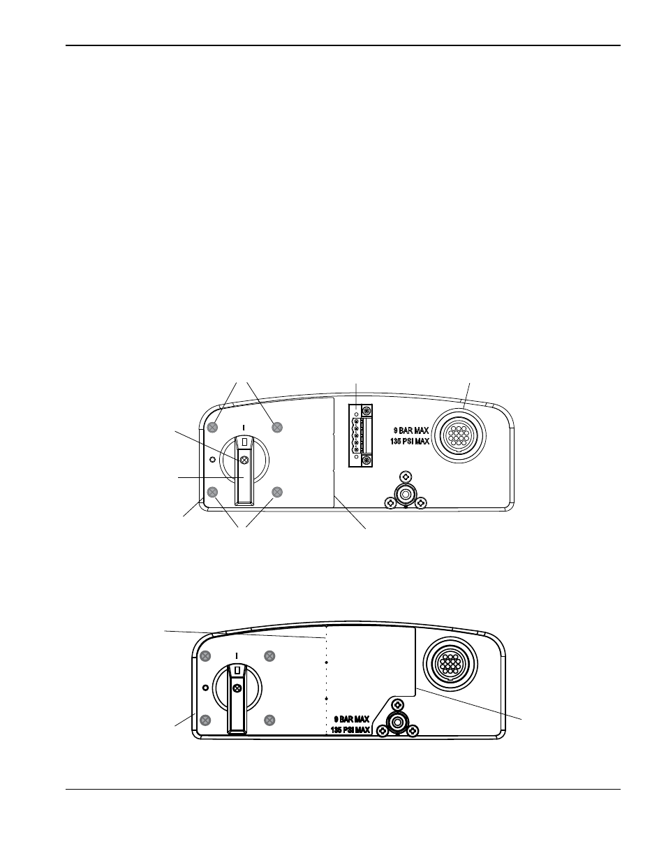
9. Remove the handle screw that secures the power switch handle to the post.
10. Pull the power switch handle straight off the post and set aside the handle and screw.
11. Pry up the edge of the power switch label using a knife or blade screwdriver. If the optional RS485 connector is not
installed, the label extends to the right side of the inlet gas fitting.
12. Peel off the entire label to expose the four mounting screws that secure the power switch to the rear end panel.
13. Disengage the power switch from the rear end panel by removing the four mounting screws.
14. Secure the new power switch to the rear end panel by tightening the four supplied mounting screws to 17.3 kg cm
(15 in.-lbs).
15. If the RS485 connector is installed, bend and tear the new label at the perforation.
16. Peel the backing off the label and affix to the rear end panel, being careful to align the hole in the label with the
corresponding hole in the rear end panel.
17. Push the new power switch handle straight onto the post and tighten the handle screw to 11.5 kg cm (10 in.-lbs).
left half of label used when RS485 connector is installed
Full label used when RS485 connector is not installed
Left edge
of label
Label
perforation
Right edge
of label
Handle screw
Power switch screws
(behind label)
Optional RS485
connector
Optional CNC
interface connector
Power switch screws
(behind label)
Left edge
of label
Right edge of label
ends at perforation
Power switch handle