Powermax, Power supply component replacement, Front end panel mounting screws – Hypertherm Powermax105 Service Manual User Manual
Page 271
Advertising
Power SuPPly ComPonent rePlaCement
powermax
105 Service Manual
9-73
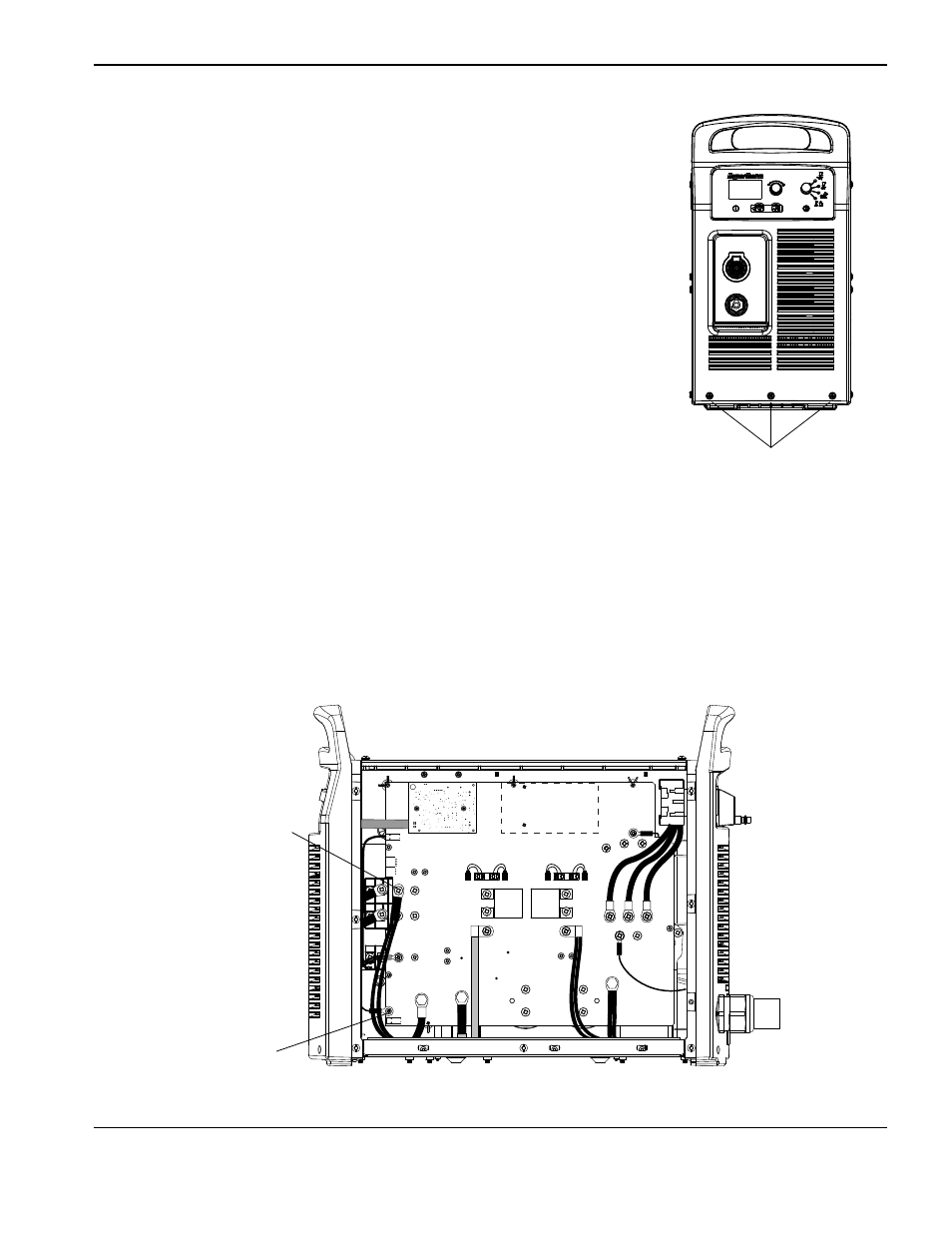
17. Carefully slide the front end panel against the power supply base.
18. Tighten the three mounting screws in the bottom of the front end panel
to 23 kg cm (20 in.-lbs).
Front end panel
mounting screws
19. Secure the electrode wire to the power board at J28 by tightening the screw to 23 kg cm (20 in.-lbs).
20. Secure the output inductor wires to the power board by tightening the screw to 40.3 kg cm (35 in.-lbs).
J22
J21
J20
J19
J27
WORK
LEAD
J26
J25
+
_
+
_
RED
J18
ORG
J17
J32
J11
B
R
J28
TP7
TP9
TP8
W
R
B
Output inductor wires
mounting screw
Electrode wire
mounting screw
Advertising
This manual is related to the following products: