Powermax – Hypertherm Powermax105 Service Manual User Manual
Page 186
TroubleshooTing and sysTem TesTs
8-48
powermax
105
Service Manual
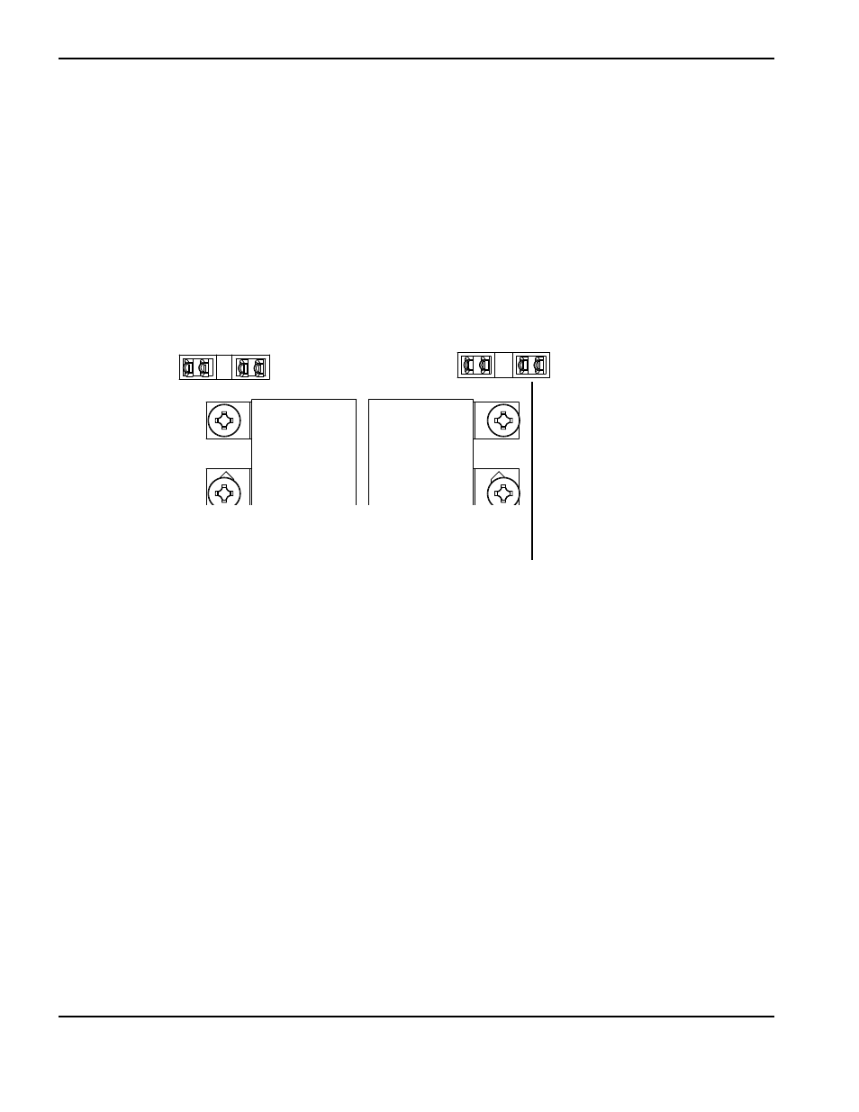
For operational fault codes 0-40-0 and 0-40-1 or power board faults 3-11-0 and 3-11-1 (CSA, 230-400 V CE,
380 V CCC/230-400 CE models only)
1. Remove PFC temperature sensor connector (J19) from power board.
2. Check the resistance between pins 1 and 2 on the plug. Resistance should be about 5 kΩ.
3. If the resistance is incorrect, replace the PFC IGBT module and gate drive cables.
4. If the value is correct, measure resistance between pins 1 and 2 on J19 on the power board with the temperature
sensor disconnected. The resistance should be about 4.7 kΩ.
5. If the value is correct, replace DSP board.
6. If the value is incorrect, replace power board.
PFC temperature sensor connection
J19
J20
J21
J22