Yaskawa Large Capacity Sigma II Series User Manual
Page 106
4 Parameter Settings and Functions
4.2.5 Using the Electronic Gear Function
4-30
3. Determine the reference unit used.
A reference unit is the minimum position data unit used to move a load. (Minimum unit
of reference from the host controller.)
• 0.01 mm (0.0004 in), 0.001 mm, 0.1
°, 0.01 inch.
A reference unit of one pulse moves the load by one reference unit.
• When the reference unit is 1
µm
If a reference of 50000 units is input, the load moves 50 mm (1.97 in) (50000
× 1µm).
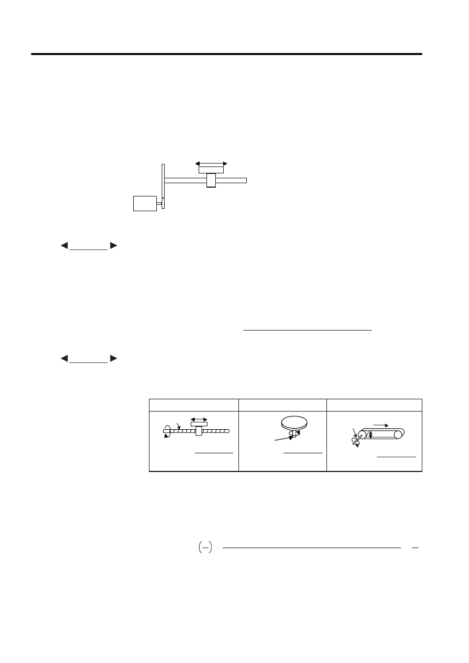
4. Determine the load travel distance per load shaft revolution in reference units.
• When the ball screw pitch is 5 mm (0.20 in) and the reference unit is 0.001 mm
(reference unit)
5. Electronic gear ratio is given as
.
If the decelerator ratio of the motor and the load shaft is given as
where m is the
rotation of the motor and n is the rotation of the load shaft,
Ball Screw
Disc Table
Belt and Pulley
Reference unit: 0.001 mm
Determine the reference unit according to
equipment specifications and positioning accuracy .
To move a table in 0.001mm units
EXAMPLE
Travel distance per load shaft revolution (reference unit)
Travel distance per load shaft revolution
Reference unit
=
EXAMPLE
5
0.001
-------------
5000
=
Load shaft
P: Pitch
P
1 revolution
=
P
reference unit
Load shaft
1 revolution
=
360˚
reference unit
D: Pulley
D
π D
Load
1 revolution
reference unit
shaft
=
π D
B
A
----
n
m
----
Electronic gear ratio
B
A
=
No. of encoder pulses
× 4
Travel distance per load shaft revolution (reference unit)
× mn