Absolute encoders, Cn2 connector terminal layout, Battery – Yaskawa Large Capacity Sigma II Series User Manual
Page 58
2.5 Wiring Encoders
2-31
2
Absolute Encoders
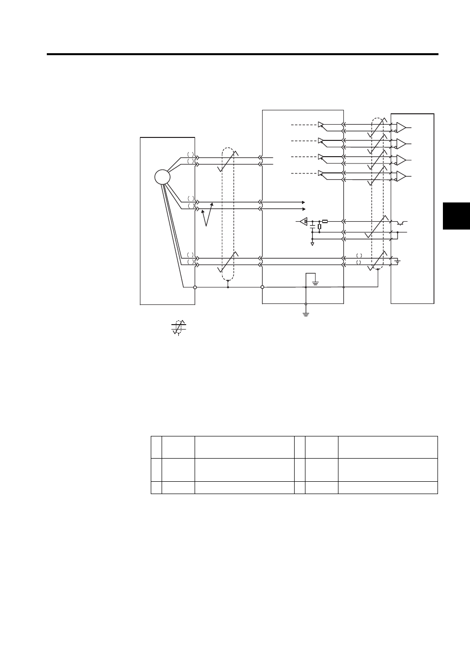
2.5.2 Terminal Layout and Types of CN2 Encoder Connector
The following diagram shows the layout and types of CN2 terminals.
CN2 Connector Terminal Layout
/PCO
PSO
/PSO
2-3
2-4
1-48
1-49
1-4
1-2
SG
SEN
+5 V
1-21
1-22
BAT +
BAT -
+
-
C 5
D 6
H 1
G 2
J
2-1
2-2
2-5
2-6
CN2
1-33
1-34
1-35
1-36
1-19
1-20
CN1
0V
0V
SG
1-1
PG5V
PG0V
PAO
/PAO
PBO
/PBO
PCO
0.33mm
2
(0.001in
2
)
Orange
White/
orange
Battery
∗
∗
T 3
S 4
PG
∗
Blue
White/Blue
Absolute encoder
Red
Black
Shield
(Shell)
Connector shell
Output line-driver
SN75ALS194 manufactured
by T/I or the eqivalent
Connector
shell
Phase A
Phase B
Phase C
Phase S
SERVOPACK
(Customer end)
Applicable line
receiver
SN75175
manufactured
by T/I or the
equivalent
: represents twisted-pair wires.
1
PG5V
PG power supply
+5 V
2
PG 0 V
PG power supply
0 V
3
BAT (+)
Battery
(+)
(For an absolute encoder)
4
BAT (-)
Battery
(-)
(For an absolute encoder)
5
PS
PG serial signal input
6
/PS
PG serial signal input