Speed reference used as detection point, Acceleration used as detection point, Example – Yaskawa Large Capacity Sigma II Series User Manual
Page 195
5 Servo Adjustment
5.2.5 Using Mode Switch
5-12
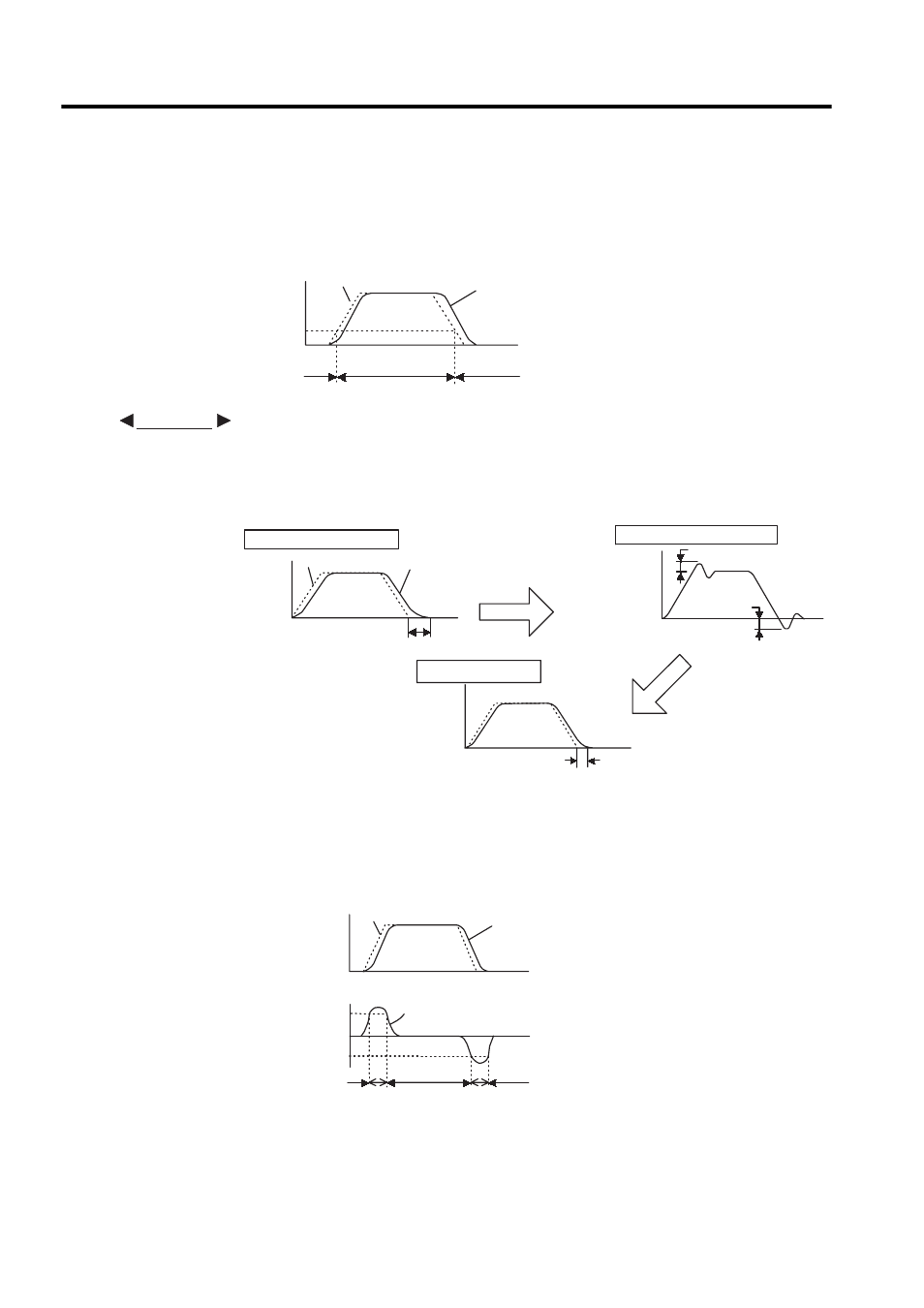
Speed Reference Used as Detection Point
With this setting, if a speed reference exceeds the value set in parameter Pn10D, the speed
loop switches to P control.
Operating Example
In this example, the mode switch is used to reduce setting time. Generally, speed loop
gain must be increased to reduce setting time. Using the mode switch suppresses the
occurrence of overshooting and undershooting when speed loop gain is increased.
Acceleration Used as Detection Point
If motor acceleration exceeds the value set in parameter Pn10E, the speed loop switches to P
control.
Speed reference
Speed
Pn10D
Motor speed
Time
P control
PI
control
PI control
EXAMPLE
Motor speed
Speed reference
Without mode switch
Long setting time
Increase speed loop gain.
Overshooting
Without mode switch
With mode switch
Setting time
Suppress overshooting
and undershooting.
Motor
speed
Motor
speed
Motor
speed
Under-
shooting
Time
Motor speed
Reference speed
Speed
Motor acceleration
+Pn10E
Acceleration 0
- Pn10E
PI control
PI control
PI control
P control
P control