Input pulse multiplier – Yaskawa Large Capacity Sigma II Series User Manual
Page 95
4.2 Settings According to Host Controller
4-19
4
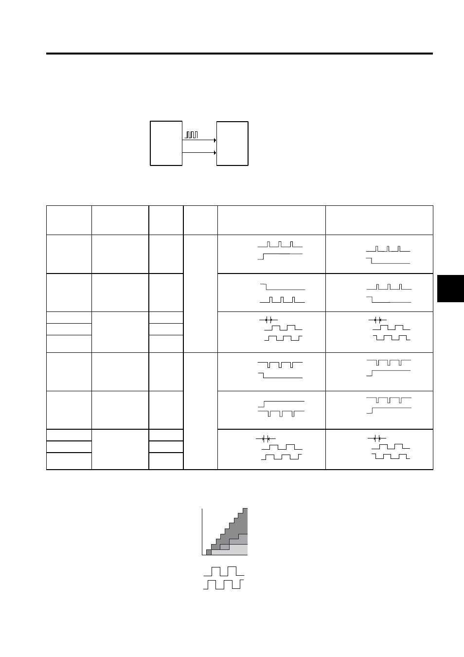
Set reference pulse form input to the SERVOPACK from the host controller.
Since the reference pulse form can be selected from among those listed below, set one
according to host controller specifications.
Input Pulse Multiplier
SERVOPACK
CN1-7
PULS
Position
reference
pulse
CN1-11
SIGN
Host
controller
Parameter
Pn200.0
Reference
Pulse Form
Input
Pulse
Multiplier
Logic
Forward Rotation Reference
Reverse Rotation Reference
0
Sign + pulse train
-
Positive
logic
1
CW pulse +
CCW pulse
-
2
Two-phase pulse
train with 90
°
phase differential
× 1
3
× 2
4
× 4
5
Sign + pulse train
-
Negative
logic
6
CW pulse +
CCW pulse
-
7
Two-phase pulse
train with 90
°
phase differential
× 1
8
× 2
9
× 4
High
PULS
(CN1-7)
SIGN
(CN1-11)
Low
PULS
(CN1-7)
SIGN
(CN1-11)
Low
PULS
(CN1-7)
SIGN
(CN1-11)
Low
PULS
(CN1-7)
SIGN
(CN1-11)
90˚
PULS
PULS
(CN1-7)
SIGN
1)
(CN1-1
90˚
PULS
PULS
(CN1-7)
SIGN
1)
(CN1-1
Low
PULS
(CN1-7)
SIGN
(CN1-11)
High
PULS
(CN1-7)
SIGN
(CN1-11)
High
PULS
(CN1-7)
SIGN
(CN1-11)
High
PULS
(CN1-7)
SIGN
(CN1-11)
90˚
PULS
PULS
(CN1-7)
SIGN
1)
(CN1-1
90˚
PULS
PULS
(CN1-7)
SIGN
1)
(CN1-1
Number of
servomotor
move pulses
× 4
× 2
× 1
8
6
4
2
0 Input reference pulse
PULS
(CN1-7)
SIGN
(CN1-11)