Internal connection diagram, Connections – Yaskawa Large Capacity Sigma II Series User Manual
Page 333
Advertising
7.5 Specifications and Dimensional Drawings for Peripheral Devices
7-57
7
Internal Connection Diagram
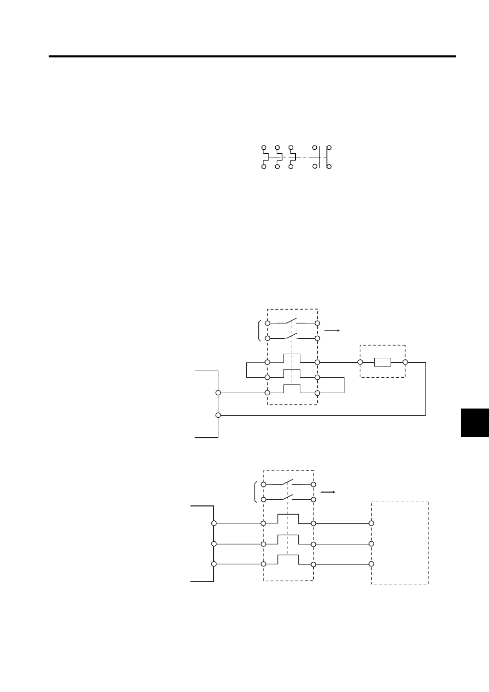
The following connection diagram is for a TR-3N Thermal Relay.
Connections
Connect the thermal relay as shown in the following diagram.
When the thermal relay operates, the auxiliary contact turns OFF (or ON). Therefore, con-
figure a sequence so that the main power supply or the servomotor turns OFF when the aux-
iliary contact turns OFF (or ON).
Connecting to a Regenerative Resistor Unit
Connecting to a Dynamic Brake Unit
1
2
3
4
5
6
97 95
98 96
(NO) (NC)
(NO) (NC)
SGDH SERVOPACK
Thermal relay
Regenerative
Resistor Unit
Auxiliary contact
To host
B1
B2
B1
B2
Thermal relay
Dynamic Brake Unit
SGDH SERVOPACK
Auxiliary contact
To host
DV
DW
DU
DW
DU
DV
Advertising