Yaskawa Large Capacity Sigma II Series User Manual
Page 381
8 Inspection, Maintenance, and Troubleshooting
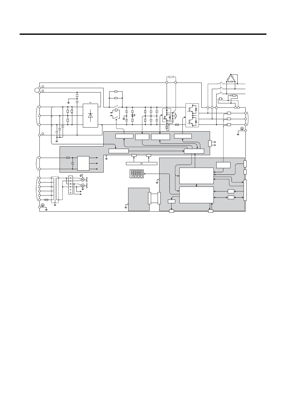
8.2.5 Internal Connection Diagram and Instrument Connection Examples
8-42
45 kW or 55 kW for 400 V
Fig. 8.3 SERVOPACK Internal Connection Diagram of 45 kW or 55 kW for 400 V
ASIC
CPU
D/A
A/D
I/O
CN5
CN3
CN10
CN2
CN8
CN1
1PCB
2PCB
+
-
+5V
+24V
+15V
43CN
3PCB
DC24P
DC24N
DV
DU
DW
MC
DCCT1
DB24
DBON
W
V
U
W
V
U
DCCT2
DCCT3
DB24
DBON
R
T
S
+
-
+
-
+
-
+
-
TRM1 to TRM6
C1 to C4
TRM4
+
-
+
-
CHARGE
MC1
MC1
R1
200 VAC
DM1
DM3
C64
C65
C61 C63
L1/R
1
2
-
L2/S
L3/T
B1
B2
+
+
FU1
FU4
FAN1
215V
1
2
3
4
480V
460V
440V
400V
380V
0
600V 4A
0
E
FAN2
5
6
200 VAC
SA1 ¡ 3
DV DU DW
MC
R2
PG
DC reactor
connection
terminals
Main circuit
power supply
input terminals
Main circuit
negative-side
terminal
380 to 480 VAC
(24 VDC)
Control power
supply input
terminals
Ground terminal
DC/DC
converter
Relay drive
Varistor
Varistor
Varistor
Voltage detection
(Option Unit)
Panel Operator
Thermostat 1
Thermostat 2
Voltage
detection
Voltage
detection
Voltage detection
gate drive
Gate drive
Interface
(PWM control, etc.)
(position/speed
calculation, etc.)
Battery
Ground
terminal
Motor
connection
terminals
Reference
pulse input
Sequence I/O
Speed/torque
reference input
Analog monitor
Digital Operator
Regenerative
resistor
Regenerative resistor unit
connection terminals