Output signal monitor display – Yaskawa Large Capacity Sigma II Series User Manual
Page 238
6 Using the Digital Operator
6.1.7 Operation in Monitor Mode
6-18
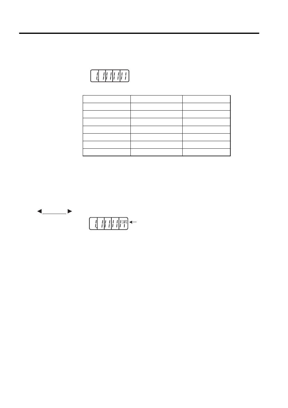
Output Signal Monitor Display
Note: Refer to 4.3.4 Output Circuit Signal Allocation for details on output
terminals.
Output signals are allocated as shown above and displayed on the panel display of the SER-
VOPACK or the Digital Operator. They are indicated by ON/OFF display of seven-segment
LEDs in top and bottom rows. These segments turn ON depending on the output signals
(ON for “L” level and OFF for “H” level).
• When ALM signal operates (alarm at “H”)
LED Number
Output Terminal Name
Factory Setting
1
(CN1-31, -32)
ALM
2
SO1 (CN1-25, -26)
/COIN or /V-CMP
3
SO2 (CN1-27,
-
28)
/TGON
4
SO3 (CN1-29, -30)
/S-RDY
5
(CN1-37)
AL01
6
(CN1-38)
AL02
7
(CN1-39)
AL03
4 3 2 1
Top: OFF ("H" level)
Bottom: ON ("L" level)
Number
7 6 5
EXAMPLE
The top segment of
number 1 is lit.
4 3 2 1
7 6 5