5 wiring encoders, Incremental encoders – Yaskawa Large Capacity Sigma II Series User Manual
Page 57
2 Basic Operation
2.5.1 Connecting an Encoder (CN2) and Output Signals from the SERVOPACK (CN1)
2-30
2.5 Wiring Encoders
The following sections describe the procedure for wiring a SERVOPACK to the encoder.
2.5.1 Connecting an Encoder (CN2) and Output Signals from the SERVO-
PACK (CN1)
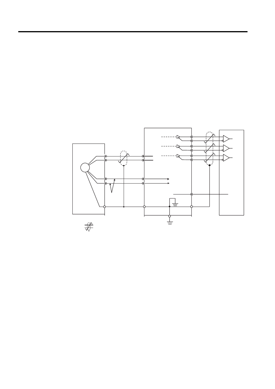
The following diagrams show wiring for incremental and absolute encoders.
Incremental Encoders
1-35
SG
1-1
0V
0V
PAO
/PAO
PBO
PCO
/PBO
/PCO
PG5V
PG0V
2-1
2-2
2-5
2-6
CN2
C (5)
1-33
1-34
1-36
1-19
1-20
PG
D (6)
H (1)
G (2)
CN1
J
0.33mm
2
(0.001in
2
)
Blue
White/Blue
Incremental encoder
Red
Black
Shield wires
(Shell)
Connector shell
Output line-driver
SN75ALS194 manufactured
by T/I or the eqivalent
Connector
shell
Phase A
Phase B
Phase C
SERVOPACK
(Customer end)
Applicable line
receiver
SN75175
manufactured
by T/I or the
equivalent
∗
∗
∗
: represents twisted-pair wires.