Internal circuits – Yaskawa Large Capacity Sigma II Series User Manual
Page 319
7.5 Specifications and Dimensional Drawings for Peripheral Devices
7-43
7
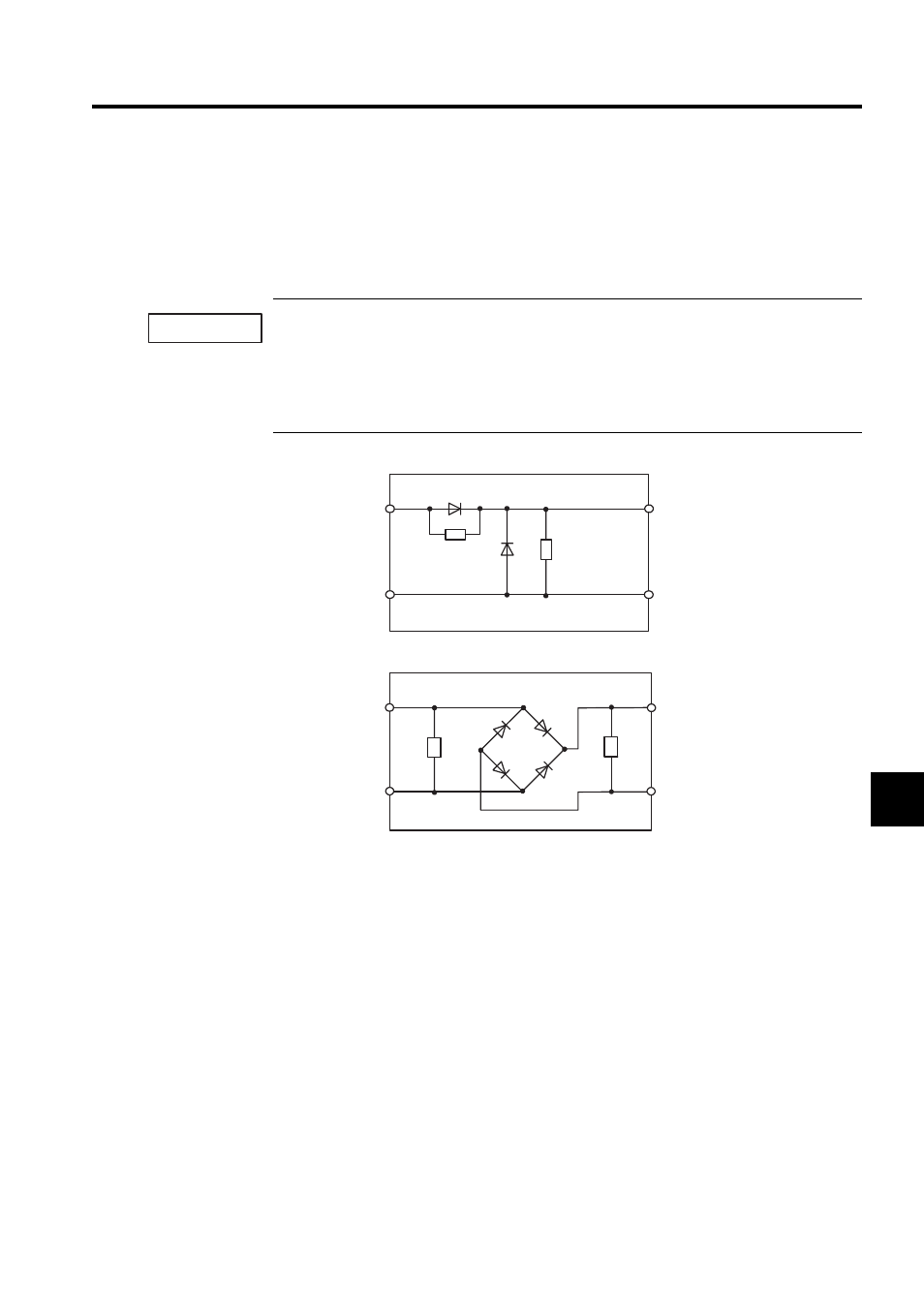
Internal Circuits
The following shows internal circuits for brake power supplies. While it is possible to switch
either the AC or the DC side of the power supplies, it is normally safer to switch the AC
side.
When switching on the DC side, install a surge suppressor near the brake coil to prevent damage to the
coil from voltage surges due to DC-side switching.
Brake operation time delay occurs during brake power supply ON/OFF operation. Set output timing of
servo OFF operation (motor output stop), referring to 4.4.4 Using the Holding Brake. Especially, if the
AC side of the brake power supply is to be switched, brake operation time is extended.
• Internal Circuit for 200 VAC Input (LPSE-2H01)
• Internal Circuit for 100 VAC Input (LPDE-1H01)
IMPORTANT
Surge
suppressor
AC side
Red
Black
Yellow
Yellow
DC (Brake) side
Surge
supressor
diode
Surge
suppressor
Diode bridge
AC side
Red
Black
Blue
White
DC (Brake) side
Surge
suppressor