Input signals torque reference inputs, Example – Yaskawa Large Capacity Sigma II Series User Manual
Page 117
4.2 Settings According to Host Controller
4-41
4
Input Signals
Torque Reference Inputs
The following input signals are used for torque control.
These signals are used when torque control is selected.
Servomotor torque is controlled so that it is proportional to the input voltage between T-REF
and SG.
• Factory Settings
Pn400 = 30: This setting means that 3 V is equivalent to the rated torque.
+3 V input: Rated torque in the forward direction
+9 V input: 300% of rated torque in the forward direction
-0.3 V input: 10% of rated torque in the reverse direction
Parameter Pn400 can be used to change the voltage input range.
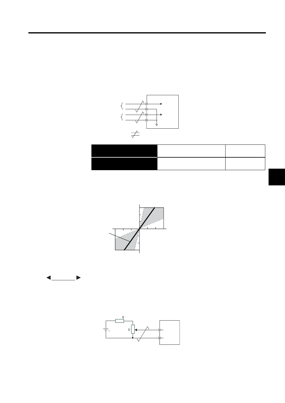
• Example of an Input Circuit
Always use twisted-pair cable for noise control.
Recommended variable resistor: Model 25HP-10B manufactured by Sakae Tsushin
Kogyo Co., Ltd.
→ Input T-REF CN1-9
Torque Reference Input
Speed/Torque
Control
→ Input SG CN1-10
Signal Ground for the Torque Ref-
erence Input
Speed/Torque
Control
Torque reference input
(Analog voltage input)
Speed reference input
(Analog voltage input)
: represents twisted-pair wires.
SERVOPACK
Torque
reference
Speed
reference
SG
V-REF
SG
T-REF
CN1-9
CN1-10
CN1-5
CN1-6
300
200
100
- 300
- 200
- 100
0
- 4
- 8
- 12
4
8
12
Reference torque (%)
Input voltage (V)
The slope is set to Pn400.
Factory setting
EXAMPLE
470
SERVOPACK
1/2W min.
SG
T-REF
+12 V
+
CN1-9
CN1-10
2k