Yaskawa Large Capacity Sigma II Series User Manual
Page 264
6 Using the Digital Operator
6.2.10 Manual Zero Adjustment and Gain Adjustment of Analog Monitor Output
6-44
6.2.10 Manual Zero Adjustment and Gain Adjustment of Analog Monitor
Output
Motor speed, torque reference, and position error can be monitored through the analog mon-
itor output. Refer to 5.5 Analog Monitor.
Use the manual zero adjustment function to compensate for the output voltage drift or the
zero point drift caused by noise entering the monitor system. The gain adjustment function
can be changed to match the sensitivity of the measuring system.
The output voltage of the analog monitor is ±8 V max. The output voltage will be reversed if ±8 V is
exceeded.
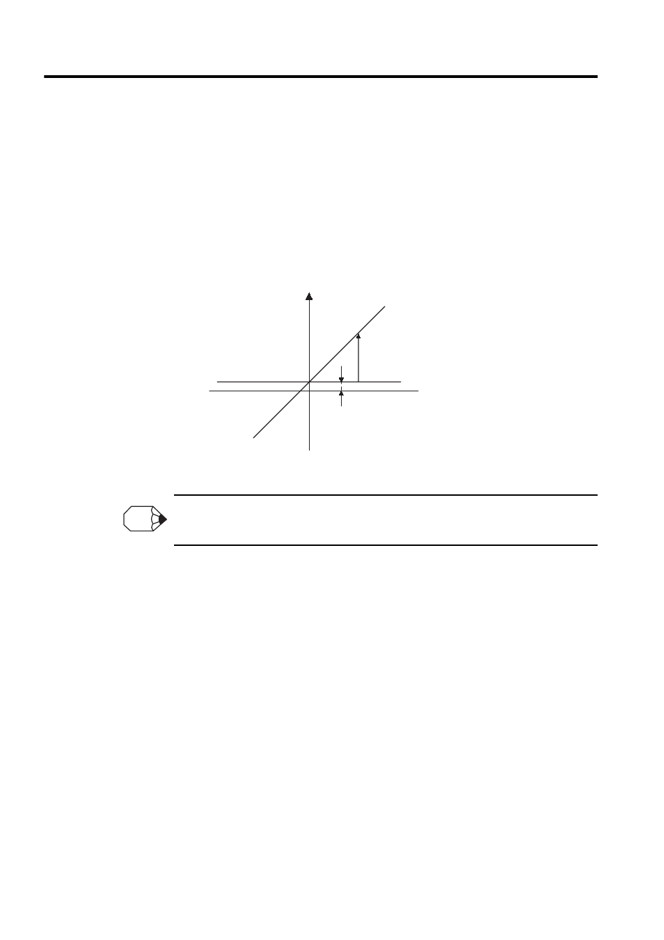
Monitor output voltage
Zero adjustment
Gain adjustment
Zero Setting Range:
± 2V
→ 17 mV/LSB
Gain Setting Range: 50 to 150%
→ 0.4 %/LSB
Setting Unit
INFO