5 absolute encoder reception sequence, Outline of absolute signals – Yaskawa Large Capacity Sigma II Series User Manual
Page 166
4 Parameter Settings and Functions
4.7.5 Absolute Encoder Reception Sequence
4-90
4.7.5 Absolute Encoder Reception Sequence
The sequence in which the SERVOPACK receives outputs from the absolute encoder and
transmits them to the host device is shown below.
Be sure you understand this section when designing the host device.
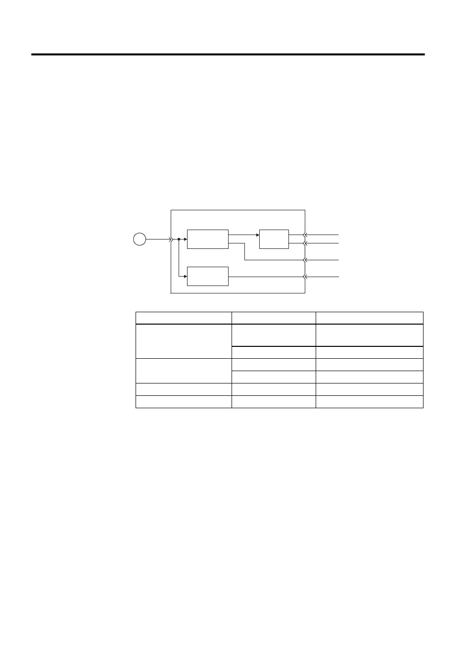
Outline of Absolute Signals
The absolute encoder’s outputs are PAO, PBO, PCO, and PSO signals as shown below.
Signal Name
Status
Signal Contents
PAO
Initial state
Serial data
Initial incremental pulse
Normal state
Incremental pulse
PBO
Initial state
Initial incremental pulse
Normal state
Incremental pulse
PCO
Always
Origin pulse
PSO
Always
Rotation count serial data
PG
SERVOPACK
Serial data
→
pulse conversion
PS
PAO
PBO
PCO
PSO
Dividing
circuit
(Pn201)
Data
→ data
conversion