Reference position input circuit – Yaskawa Large Capacity Sigma II Series User Manual
Page 54
2.4 I/O Signals
2-27
2
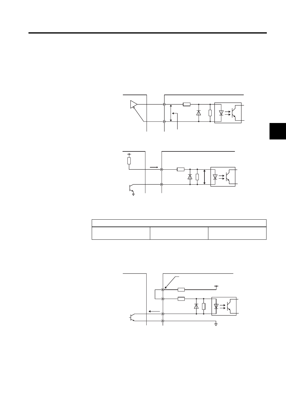
Reference Position Input Circuit
An output circuit for the reference pulse and error counter clear signal at the host controller
can be either line-driver or open-collector outputs. These are shown below by type.
• Line-driver Output
• Open-collector Output, Example 1: Power Supply Provided by User
Use the examples below to set pull-up resistor R1 so the input current, i, falls between 7
and 15 mA.
• Open-collector Output, Example 2: Using 12-V Power Supply Built into SERVOPACK
This circuit uses the 12-V power supply built into the SERVOPACK. The input is not
insulated in this case.
Application Examples
When Vcc is 24 V ± 5 %:
R1 = 2.2 k
Ω
When Vcc is 12 V ± 5 %:
R1 = 1 k
Ω
When Vcc is 5 V ± 5 %:
R1 = 180
Ω
2 . 8 V
≤ (H level)
− (L level) ≤ 3.7 V
150
Ω
4.7k
Ω
Applicable line-driver
SN75174 manufactured
by T/I or the equivalent
Host controller end
SERVOPACK end
SERVOPACK end
V
F
= 1.5 to 1.8 V
150
Ω
4.7 k
Ω
Vcc
Tr1
V
F
R1
i
Host controller end
Host controller end
PL1,PL2,PL3, terminals
0V
+12V
1.5V max.
when ON
About
9 mA
1.0 k
Ω
150
Ω
SERVOPACK end