Electronic gear setting examples, Ball screw disc tables belts and pulleys – Yaskawa Large Capacity Sigma II Series User Manual
Page 108
4 Parameter Settings and Functions
4.2.5 Using the Electronic Gear Function
4-32
Electronic Gear Setting Examples
The following examples show electronic gear settings for different load mechanisms.
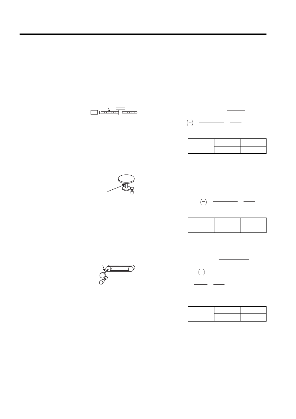
Ball Screw
Disc Tables
Belts and Pulleys
Preset
Values
Pn202
8192
Pn203
6000
Preset
Values
Pn202
24576
Pn203
3600
Ball screw pitch: 6mm (0.24in)
13-bit incremental
encoder
Load shaft
Reference unit: 0.001 mm
Travel distance per load shaft revolution =
6 mm
0.001 mm
= 6000
Electronic gear ratio B
A
= 2048 × 4 × 1
6000
× 1
= Pn202
Pn203
(0.00004 in)
Incremental encoder:
13-bit
Load shaft
Travel distance per load shaft revolution = 360 ∞
0.1∞
= 3600
Electronic gear ratio B
A
= 2048 × 4 × 3
3600
× 1
= Pn202
Pn203
Reference unit: 0.1∞
Deceleration
ratio: 3:1
Load shaft
Travel distance per load shaft revolution = 3.14 × 100 m m
0.02 m m
= 1570 0
Electronic gear ratio B
A
= 16384 × 4 × 2
1570 0
× 1
= P n202
P n203
Deceleration
ratio: 2:1
Reference unit: 0.02 mm (0.0008 in)
Pulley diameter:
φ100mm
Set a PG dividing ratio equivalent
to 16 bit for the absolute encoder
.
= 1310 72
1570 0
= 32768
3925
Preset
Values
Pn202
32768
Pn203
3925