Installation – Areca ARC-8050T3U 6-Bay Thunder3 Desktop RAID Storage Array User Manual
Page 21
INSTALLATION
21
•
Disk Slot Numbers
To perform a disk hot-plug procedure, you must know the physical
disk slot number for the drive that you want to install or remove.
The number on the drive tray shows how RAID subsystem disk
slots are numbered. Disk slot number is reflected in the RAID
manager interface. The sequence of disk slots goes from the top
of the enclosure to the bottom, from left to the right. (as shown
in storage front view figures)
•
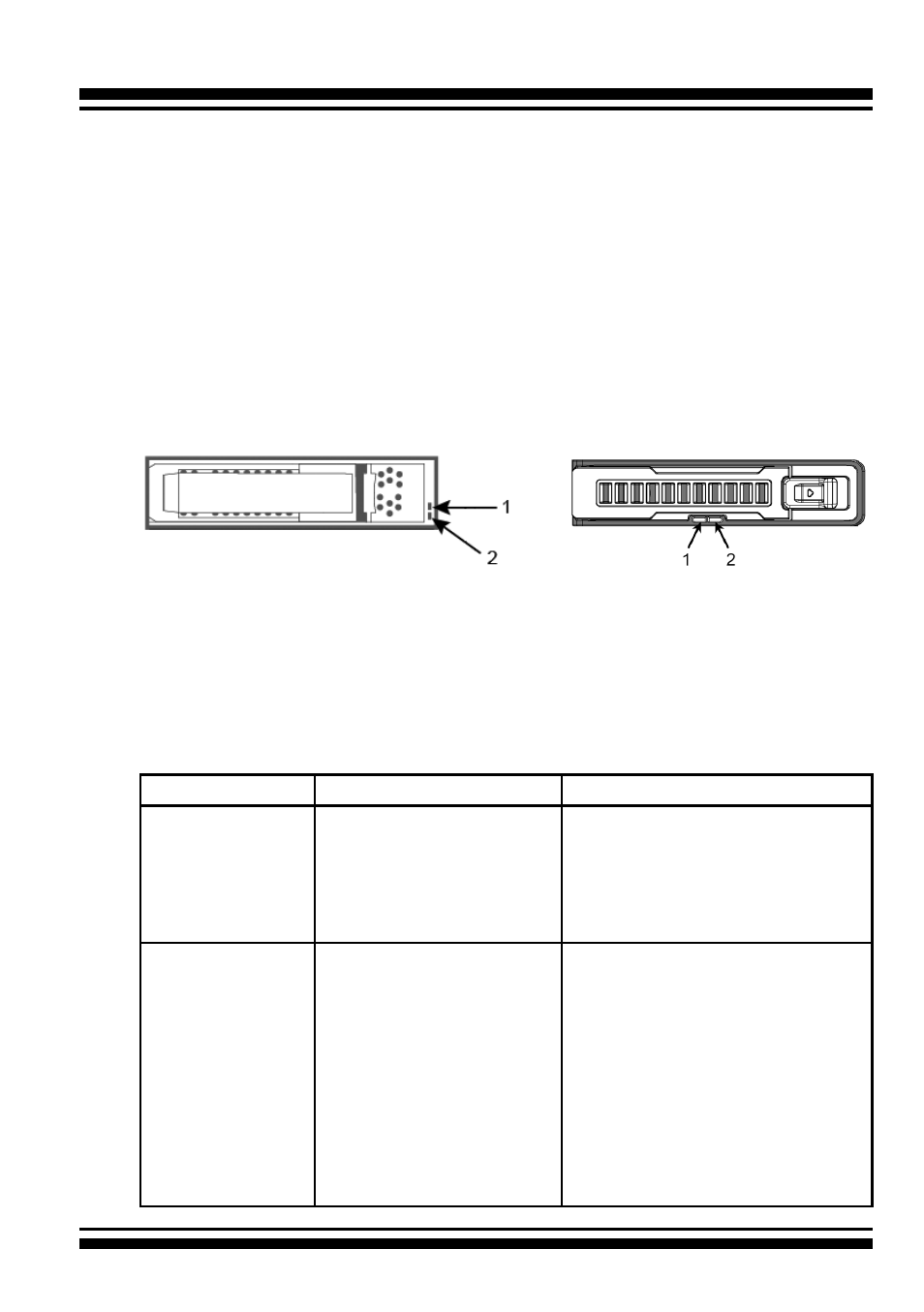
Drive Tray LED Indicators
Figure 2-1, Activity/Fault LED
(ARC-8050T3U-4/6/8/12)
Figure 2-2, Activity/Fault LED
(ARC-8050T3U-6M)
The following table describes the RAID storage disk drive tray LED
behavior.
Tray LED
Normal Status
Problem Indication
1. Activity LED
(Blue)
1. When the activity LED
is lit, there is I/O acti-
vity on that disk drive.
2. When the LED is not
lit; there is no activity
on that disk drive.
N/A
2. Fault/Link LED
(Red/Green)
1. When the fault LED is
lit, there is no disk
present.
2. When the link LED is
lit, there is a disk pre-
sent.
1. When the fault LED is off, the
disk is present and status is
normal.
2. When the fault LED is blinking
(2 times/sec.), the disk drive
has failed and should be hot-
swapped immediately.
3. When the activity LED is lit
and fault LED is fast blinking
(10 times/sec.) there is re-
building activity on that disk
drive.