AMETEK XG Family Programmable DC User Manual
Page 135
Remote Operation
M370430-01 Rev E
5-3
5
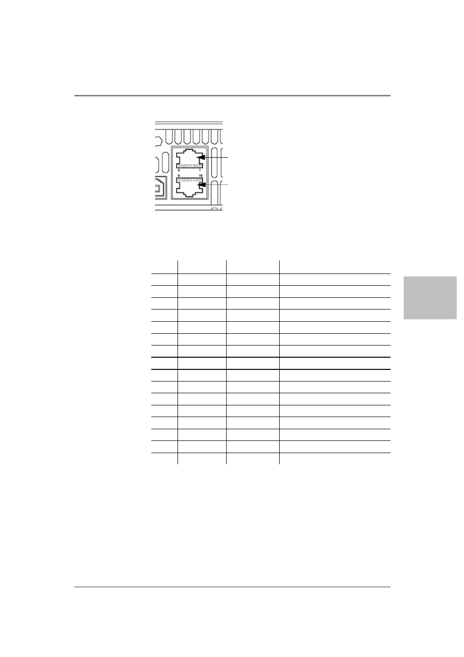
J4:
RS-232 and RS-485
connector in port
J6:
RS-232 and RS-485
connector out port
Figure 5-1
Remote Control Connectors
Table 5-1 Remote Control Connector Pins and Functions J4 and J6
1
Pin
Reference
Direction
Function
J4.1
RX-232
Input
RS-232
J4.2
TX-232
Output
RS-232
J4.3
RXD+
Input
RS-485 receiving
J4.4
RXD-
Input
RS-485 receiving
J4.5
TXD+
Output
RS-485 transmitting
J4.6
TXD-
Output
RS-485 transmitting
J4.7
GND
–
Ground
J4.8
NC
–
–
J6.9
NC
–
–
J6.10
NC
–
–
J6.11
RXD+
Input
RS-485 receiving
J6.12
RXD-
Input
RS-485 receiving
J6.13
TXD+
Output
RS-485 transmitting
J6.14
TXD-
Output
RS-485 transmitting
J6.15
GND
–
Ground
J6.16
NC
–
–
1. All references and directions indicated in this table are with respect to the
XG.