AMETEK XG Family Programmable DC User Manual
Page 140
Remote
Operation
5-8
M370430-01 Rev E
RS-485 Communication Cable with Two RJ-45s
Use the top connector of the two 8-pin RJ-45 jacks, as shown in Figure
5-1, to connect to the RS-485 remote interface. Communication cable
with two RJ-45 shielded connectors (see
Figure 5-3)
connecting the
master unit to the slave unit. The cable length should be 9.84 feet (3 m)
or less. The pinouts for the RJ-45 plug on the master unit are the same as
described in Table 5-7
.
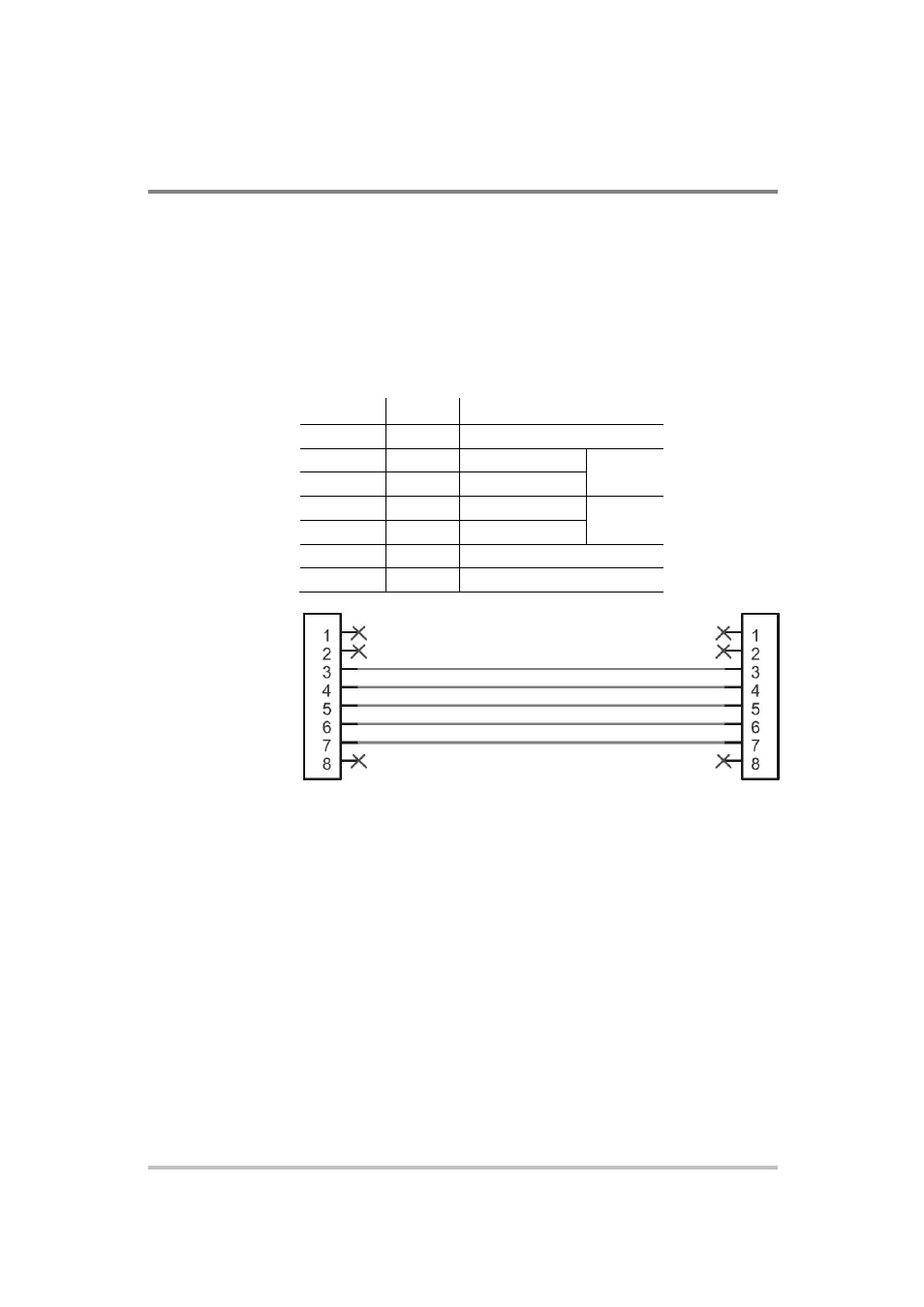
Table 5-7 RJ-45 Plug on Slave Unit
Pin
Name
Description
1, 2
NC
No connection
3
RXD+
Receive data
Twisted
pair
4
RXD-
Receive data
5
TXD+
Transmit data
Twisted
pair
6
TXD-
Transmit data
7
GND
Ground
8
NC
No connection
Master unit (J6)
Slave unit (J4)
Figure 5-6
RS-485 Communication Cable from Master to Slave Unit
Completing the Setup
To complete the setup:
Configure the XG to use the 485 remote interface and setup the
terminal that will be used on the connected PC.
See sections entitled “Selecting the Appropriate Communication
Port” on page 5-24 and “Terminal Configuration” on page 5-21 for
more details.
RXD+
RXD–
TXD+
TXD–
GND
RXD+
RXD–
TXD+
TXD–