Connecting single loads, Connecting multiple loads – AMETEK XG Family Programmable DC User Manual
Page 44
Installation
2-14
M370430-01 Rev E
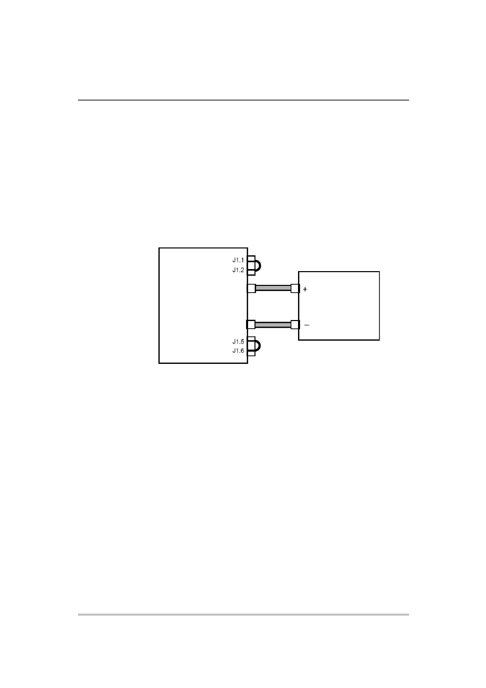
Connecting Single Loads
Figure 2-3 shows the recommended load connections for a single
load which is sensing its voltage locally. Local sense lines shown
are the default connections at the rear panel APG J1 connector (see
Figure 4-1 on page 4-5). The load lines should use the largest
gauge and shortest length of wire possible to ensure optimal
performance.
You do not need remote sensing for basic operation of your power
supply. However, if you wish to correct any small drops in your
load lines, then use the remote sensing feature. See “Step 7:
Connecting Remote Sensing” on page 2-15 for more information.
Figure 2-4
Connecting Single Loads
Connecting Multiple Loads
The proper connection of distributed loads is an important aspect of
power supply use. The common method of connection is a radial load
connection. Power is connected to each load individually from a single
pair of terminals designated as the positive and negative distribution
terminals. This pair of terminals may be the power supply output
terminals, the load terminals, or a distinct set of terminals especially
established for distribution use. In this scheme, there are no ground
loops and the effect of one load upon another is minimized.
Terminal
Power Supply
Terminal
Load
– Local Sense
+ Output
+ Local Sense
– Output