AMETEK XG Family Programmable DC User Manual
Page 210
Advertising
Communications
Options
6-4
M370430-01 Rev E
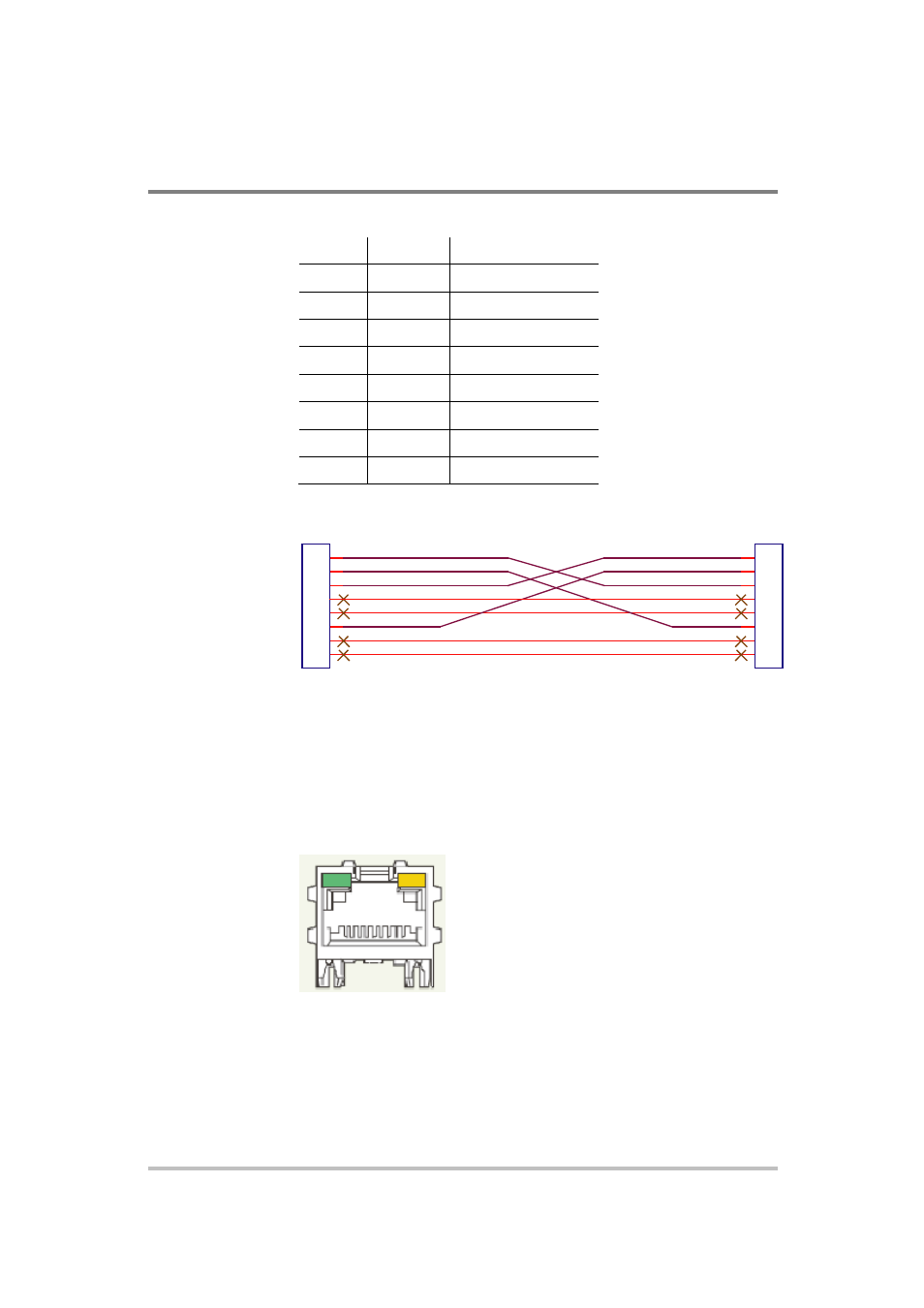
Table 6-1 Description of Pins on RJ-45 Plug
Pin#
Name
Description
1
TX+
Transmit data +
2
TX–
Transmit data –
3
RX+
Receive data +
4
Gnd
Ground
5
Gnd
Ground
6
RX–
Receive data –
7
Gnd
Ground
8
Gnd
Ground
1
2
3
4
5
6
7
8
1
2
3
4
5
6
7
8
TX+
TX-
RX-
RX+
Figure 6-4 Scheme of ENET Cross-Cable
ENET Connector
The XPort® ENET connector is located on the rear panel of the power
supply. See Figure 6-5. At the top left corner is the link LED, and at the
top right corner of the connector is the activity LED. See Table 6-2 for a
description of their colors and what each indicates.
Figure 6-5 XPort® ENET Connector and LEDs
Advertising
This manual is related to the following products: